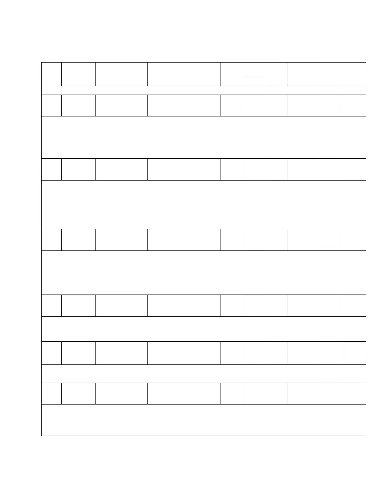
TABLE 5-3. Function Codes (continued)
Func.
Code
Level 1
Main Menu
Level 2
Sub-Menu
Level 3
Parameter
Security Level Factory
Setting
Key Entry Limit
Read Edit Reset Low High
47 Features Calibration 047 Voltage
Calibration
110.0 Volts
0 3 NA See Note 110.0 130.0
• The voltage which the control actually measures is displayed at FC 47. In the example given in FC 44 description, FC 47
would indicate 125.1 V when FC 6 indicated 120 V.
• To calibrate, this value is compared to a reference voltmeter and, if different, is changed to display the correct value.
• Note: A default calibration factor is programmed into non-volatile memory at the factory and should not be necessary in the
field.
• See the Troubleshooting: Control Calibration section of this manual.
48 Features Calibration 048 Current
Calibration
100.0 mA
0 3 NA See Note 100.0 400.0
• The current which the control actually measures, in mA, is displayed at FC 48.
• The control is designed for 200 mA as the rated CT secondary output current and will meter to 400 mA (200% load) with no
loss of accuracy.
• To calibrate, this value is compared to a reference ammeter and, if different, is changed to display the correct value.
• Note: A default calibration factor is programmed into non-volatile memory at the factory and should not be necessary in
field.
• See the Troubleshooting: Control Calibration section of this manual.
49 Settings Configuration 049 Tap Changer Type
Cooper QD8
0 2 NA See Note NA NA
• This function code identifies the tap-changer type. See Service Information S225-10-10. Changing this function code changes
the control’s sampling rate to accommodate varying tap-changer types.
• Options include:
• Cooper QD8 • Cooper QD5 • Cooper QD3 • Cooper Spring Drive • LTC Reinhausen
• Cooper Direct Drive • Siemens • General Electric • Howard • None
Note: The LCD will display "_ _ _ _" (Invalid) if this is set to "None".
50 Settings Calendar/Clock 050 System Calendar
and Clock
(Date / Time shown)
0 3 NA NA NA NA
• The system date and time utilizes the MM/DD/YYYY and 24-hour format.
• The default is Jan. 1, 1970.
• Refer to the Control Features: Calendar/Clock section of this manual for more information.
51 Settings Reverse
Direction
051 Reverse
Set Voltage
120.0 Volts
0 2 NA 120.0 100.0 135.0
• The set voltage is the voltage level to which the control will regulate, on the 120 V base, during reverse power flow.
• See FC 1 and the Control Features: Reverse Power Operation section of this manual.
52 Settings Reverse
Direction
052 Reverse
Bandwidth
2.0 Volts
0 2 NA 2.0 1.0 6.0
• The bandwidth is defined as that total voltage range, around the set voltage, which the control will consider as a satisfied (in-
band) condition, during reverse power flow.
• Example: A bandwidth of 3.0 V and a set voltage of 120.0 V will establish a low limit of 118.5 V and a high limit of 121.5 V.
• See FC 2–FC 5 and the Control Features: Reverse Power Operation section of this manual.
51
CL-6 SERIES CONTROL INSTALLATION, OPERATION, AND MAINTENANCE INSTRUCTIONS MN225016EN January 2016
 Loading...


