22. Verify that:
A. The V1 and V6 knife blade switches are open.
B. The C knife blade is closed (shorted).
23. If not already installed, install the control panel on the
hinges and plug in the connector
24. Proceed to Control Setup section of this manual.
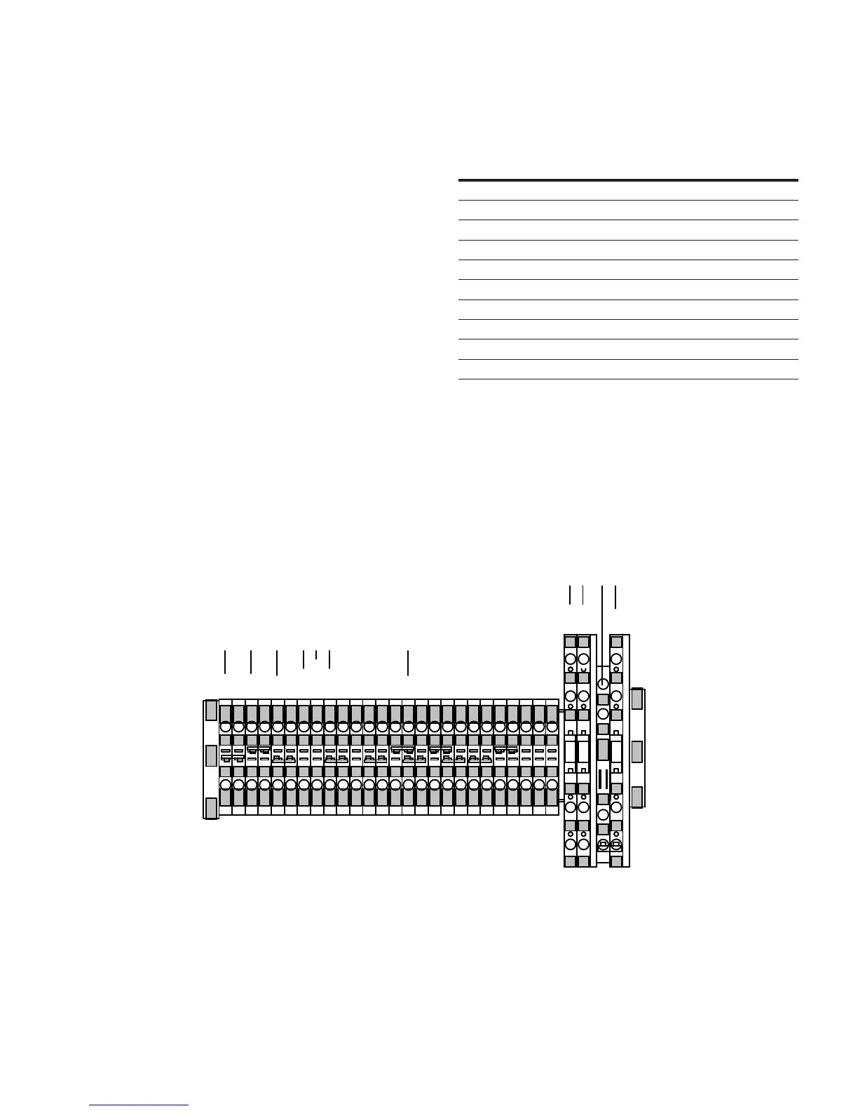
Table 3. CRA Kit Connections to a Howard Voltage
Regulator
Eaton Labels Howard Connections
G G
R R
L L
OC OC
DHR DHR
NL NS
V6* MS
V1 PS
C Switch Top C
C Switch Bottom CO
(G)
(R)
(R)
(L)
(L)
(OC)
(DHR)
(NL)
(NL)
(NL2)
(HS)
(HS)
(#2)
(G)
(G)
(#1)
(V2)
(V5)
(V1)
(V4)
(C2)
(C3)
(20)
(21)
(23)
(G)
(V6)
(V1)
(C)
G
R
L
DHR
NS
OC
MS
PS
C
CO
G
* If the MS lead is used as a motor power source, it will not be used. The
motor power and sensing voltage sources will both be supplied to the
control through the PS lead.
Figure 10. TB1 Howard connections.
13CL-7 control replacement assembly installation instructions and service information MN225017EN October 2016

 Loading...


