•
Clean and lubricate PUSH-OP bushing adapter interfaces.
•
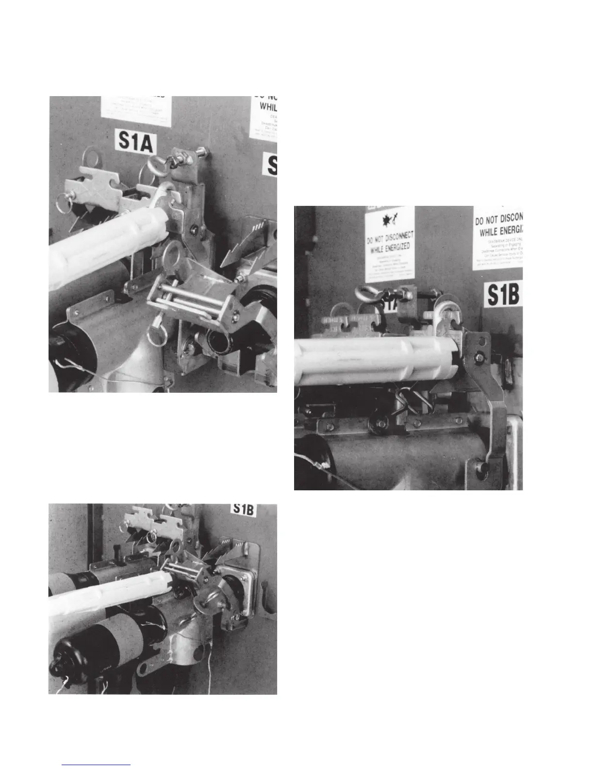
Grasp PUSH-OP bushing adapter operating eye with
hotstick. Pull eye completely into hotstick and place
adapter on exposed PUSH-OP apparatus bushing, engag-
ing shroud locating pins in bail bracket locking slots and
push until latch plate engages first notches. Refer to
Figure 13.
•
Push forward on push plate with hotstick until a bump is
felt and latch plate has engaged locking teeth.
•
Pull on push plate with hotstick to ensure that latch plate
is engaged. Refer to Figure 14.
•
Place insulated protective cap on 200 A interface using
hotstick.
•
Thread hitch pin clockwise until bail lock is secured.
Complete Steps 2 through 4 for all three phases at both
ends of cables.
Figure 12. Pull on push plate to ensure latch plate is
engaged.
Figure 13. Install adapter on PUSH-OP apparatus bushing.
Figure 14. Pull on push plate to ensure latch plate is
engaged.
6 600 A PUSH-oP DeADbreAk connector oPerAtion inStrUctionS MN650011EN May 2017

 Loading...


