11
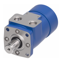
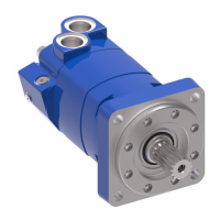
2000 Series Disc Valve Motors
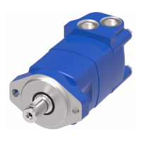
2000 SerieS diSc valve geroler motor C-MOLO-TM010-E1 June 2018 www.eaton.com
Reassembly — Speed sensor
1. Rotate the motor shaft until a (gear/
target) tooth is centered in the speed
sensor port. If this is not done, the
sensor may be damaged during the
operation of the motor.
2. Make sure the lock nut and its threads
are clean and dry for the proper
torque. Position the lock nut against
the alignment nut as shown in Figure
22.
3. Move the washer and the o-ring
up against the speed sensor body
threads as shown in Figure 22.
4. By hand, lightly thread the speed
sensor body into the housing until
the sensor touches against the motor
(gear/target) tooth.
Do not force the sensor against the
(gear/target) tooth, damage may
occur. Make sure the o-ring or the
washer do not touch the housing —
see Figure 23.
5. Turn the speed sensor body out one
quarter turn (CCW) plus the additional
amount (CCW) needed to make the
alignment notches perpendicular to
the motor shaft centerline (90° +/-5
degrees from the motor shaft center-
line — Figure 24 and 25).
6. Maintain the speed sensor body
alignment (Figure 25), and tighten
the lock nut to 8,5-14 Nm [75-125
lb-in.] (torque values are for clean dry
threads).
7. Check the speed sensor body for
correct alignment (Figure 25), reinstall
the sensor if it is not correct.
90
Alignment Notch
Alignment Notch
Alignment Notch
Speed Sensor Body
Speed Sensor Installation
Figure 24. Figure 25.
Figure 26.
Alignment Notchs
Perpendicular to
Centerline of Motor
Alignment Nut
9/16 inch
Hex Head
Lock Nut
11/16 inch
Hex Head
Parallel with
Centerline of Motor Shaft
Alignment Nut
Speed Sensor Port
Lock Nut
Housing
Back out
Gear/Target
Tooth
Washer
O-ring
 Loading...