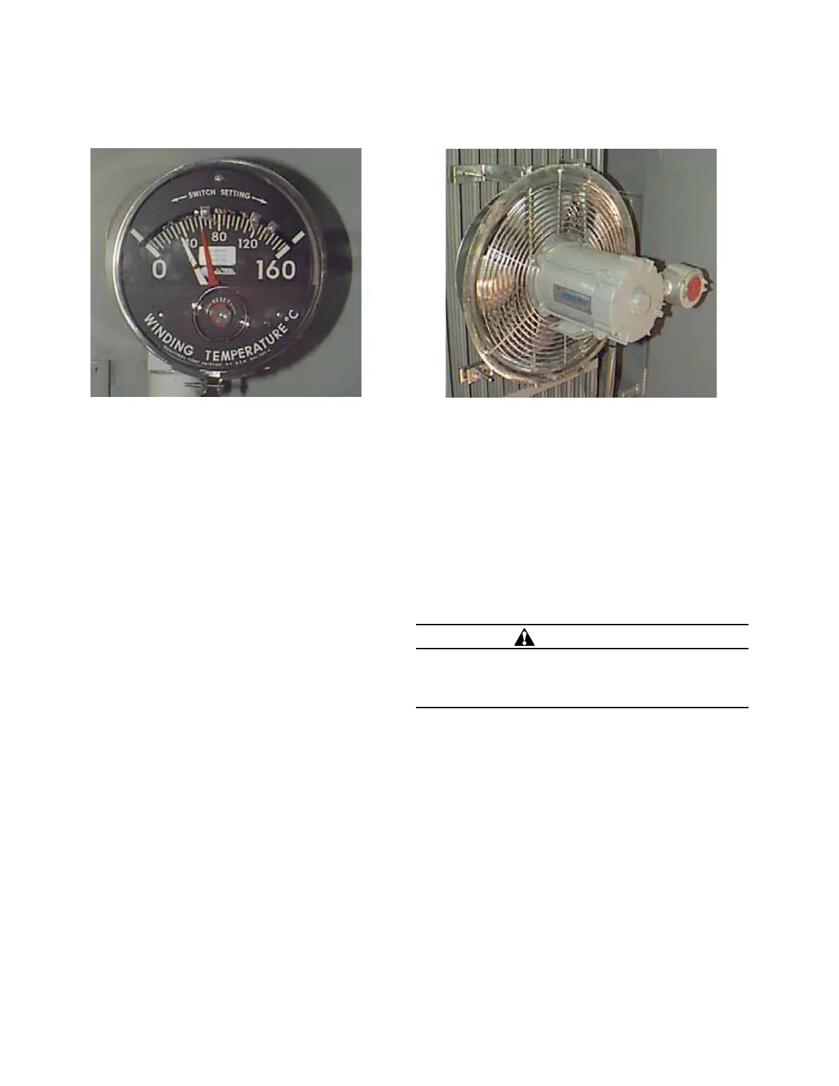
Winding temperature gauge
Transformers may be furnished with a winding temperature
gauge as optional equipment. A temperature sensitive
stem is mounted in a leakproof well, permitting removal of
both the instrument and stem without lowering the liquid
level. The well is heated by both the surrounding liquid
and a heater element which is energized from a current
transformer mounted inside the tank to simulate the hot
spot winding temperature gradient. The combination of the
two temperatures is indicated on the gauge. An additional
red pointer is furnished to show the highest temperature
attained since the last reset. The maximum indicator is
resettable by means of a pushbutton through the bottom of
the dial bezel.
The gauge has three separate SPDT switches for fan control
and alarm circuits. For wiring the contact settings, refer to
the schematic furnished with the transformer.
The equipment is calibrated to indicate the hottest spot
of the transformer windings. All contacts are factory set
to operate at the temperatures shown in the connection
diagram.
If readjustment of the contacts is desired, consult the
factory for detailed instruction.
Transformer cooling fans
In order to increase the transformer load without
overheating the windings, a set of fans can be furnished as
an optional item. Fan control consists of a contact on either
the liquid temperature gauge or the winding temperature
gauge (when furnished), and "Manual-Auto" control switch.
For continuous run, the switch is turned to the "Manual"
position. In the "Auto" position, the fans are controlled by
the contacts on the temperature gauge. For contact and
temperature settings, refer to the schematic furnished with
the transformer.
WARNING
Fan guards are furnished and installed for your
protection. Do not remove fan guards or probe into
the fan with long objects. Doing so can result in severe
personal injury and equipment damage.
Refer to wiring schematic for control equipment supplied.
Figure 5. Winding temperature gauge.
Figure 6. Transformer cooling fan.
6 SubStation tranSformer inStallation and partS replacement information MN202002EN JUNE 2016
 Loading...


