CRA kit components supplied
The following is a list of the components supplied in a
standard* kit:
•
CL-7 voltage regulator control
•
Service Information MN225003EN, CL-7 Voltage Regulator
Control Installation, Operation, and Maintenance
Instructions
•
B225-12017, CL-7 Control Reference card
•
Control box (Figure 3)
•
Universal Mounting bracket and associated hardware
(Figure 3)
•
Back panel with associated wiring (Figure 2)
•
Universal terminal designation decal. This decal provides
termination point instructions for applicable voltage
regulators and is located on the bottom of the control
box. (See Figure 1.)
•
Back Panel Tool (Figure 4)
*Components included may vary for non-standard kit assemblies.
Tools and materials required
•
Socket wrench set
•
Combination wrench set
•
Material for marking wires
•
Large adjustable wrench
•
Phillips screwdriver
•
Standard screwdriver
•
Wire cutter
•
Wire stripper
•
Tools to modify control cable conduit if applicable
Before getting started
•
Insure that all required tools and components are
available.
•
Identify the manufacturer of the regulator.
•
Determine applicable control settings: note settings from
control being replaced.
•
Test the regulator for normal operation with the existing
control panel and resolve any operational issues.
•
Inspect the control cable for signs of damage and replace
if necessary.
Installation
Making connections to the CRA
The CRA connections are made to terminal board TB1,
located on the top of the back-panel; see Figure 2. A color-
coded wiring decal clearly identifies connections; see Figure
1.
Connecting the leads to the terminal board requires using
the tool supplied with the CRA assembly or an acceptable
substitute; see Figure 4.
To use the tool, place it in the square hole next to the round
hole where a wire is to be connected. Push the tool firmly
into the hole to release the connector. Place the bare wire
of the lead into the round hole, remove the tool from the
square hole, and check the wire to make sure it is properly
placed and is tight in the terminal board. Refer to Figure 5
for placement of the tool and the wire in the terminal board.
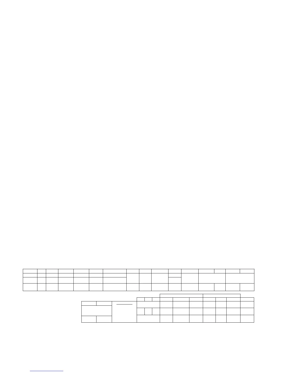
Label G R L OC DHR 2 G 1 V2 V5 V1 V4
Siemens E J K U10 U11
E
G.E. 10 27 28 30 29
SOURCE
CONN.
26 or 10
SOURCE
CONN.
REG. LOAD
FROM RCT 1
Cooper G RAISE LOWER OPCNTR DHR
2 G 1
V5
VRCT
V4
KnifeSwitches - Top Knifeswitches – Bottom
20 21 22 V6 V1 C V6 V1 C
G.E. UNIT
ONLY
U2 P2 C2 E1
20 21 22 32
20,21 or 22
Black
20AWG
White
20AWG
G.E. UNIT
ONLY
JBB-S4 JBB-S2 JBB-C2 JBB-C1
1
VRCT
2
REG.
SOURCE
FROM RCT 2
C2 C3
C2 C3
CAUTION:
DO NOT
OPEN CT
CIRCUIT
UNDER
CT HIGH
FOR
ACCESSORY
NL2
CPS
UNIT
ONLY
NEUT
LT
HS
HS
NL
U12
31
SIEMENS/GE
UNITS ONLY
CPS
UNIT
ONLY
Label
Siemens
G.E.
Cooper
Figure 1. Wiring identification decal.
2 CL-7 control replacement assembly installation instructions and service information MN225017EN October 2016
 Loading...


