Do you have a question about the Eaton Green Motion and is the answer not in the manual?
Crucial safety warnings and precautions for installation.
Guidelines for proper grounding of the EV charging equipment.
Step-by-step guide to connecting the EV smart breaker charger.
Instructions for inserting conductors into the loadcenter.
This document is an installation guide for Eaton's Green Motion EV smart breaker chargers, specifically focusing on the EV direct connect and junction box kits. It provides comprehensive instructions for installing, operating, and troubleshooting these electric vehicle (EV) charging solutions.
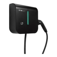
The EV smart breaker charger is designed for charging plug-in hybrid and all-electric vehicles, adhering to the Society of Automotive Engineers (SAE) J1772 charging standard. It offers advanced features beyond traditional thermal-magnetic protection. These include protection from ground faults with automatic reset, eliminating the need for user interaction. The charger also intelligently instructs the vehicle on the appropriate current draw to prevent circuit overload. Furthermore, it incorporates interlocked power protection, ensuring that power is only available at the connector when it is properly plugged into an electric vehicle, enhancing user safety.
Two main installation kits are covered: the EV direct connect kit and the EV direct connect + junction box kit. The direct connect kit is designed for installation directly into Eaton BR loadcenters or PRL3X panelboards, ideally located close to where the electric vehicle is parked. The junction box kit, on the other hand, also installs into BR loadcenters or PRL3X panelboards but includes a junction box, making it suitable for situations where the electric vehicle is parked further away from the main electrical panel.
The installation process involves several key steps. First, the EV smart breaker charger is connected. This requires disconnecting power to the loadcenter or panelboard, removing the deadfront, and ensuring the breaker handle is in the OFF position. The white "pigtail" conductor from the circuit breaker is connected to the neutral bus terminal, and the green "pigtail" conductor is connected to panel ground, with emphasis on secure connections according to designated torque specifications. The EV smart breaker charger is then installed into the desired location in the loadcenter/panelboard, either by screwing it into the "LINE" bus for BAB bolt-on devices or plugging it in for BR plug-on devices.
Next, conductors from the EV connector or junction box are inserted into the loadcenter. This involves installing an NM/SE connector for the EV connector cord or junction box conductors at a loadcenter knockout. For the direct connect kit, the EV connector is then connected. After the smart breaker charger is installed and the loadcenter deadfront is attached, power is energized. The EV smart breaker charger electronics should power up, indicated by a blinking BlinkUp™ status LED and blinking indicator LEDs on the EV connector. If no LEDs are on, it suggests a lack of power to the EV connector. Finally, the EV smart breaker charger handle is moved from the OFF to the ON position to activate charging.
For the junction box kit, the process involves connecting the EV smart breaker charger and the EV connector via the junction box. The junction box cover is opened and mounted to the wall. Appropriate 3/4-inch junction box knockouts are removed to insert the EV smart breaker charger conductors and EV connector cord. An NM/SE connector is installed in the knockout for the EV connector cord, which is then threaded through. All conductors from the EV connector are terminated to the terminal blocks within the junction box, matching conductor colors to terminal block colors. The NM/SE connector is tightened. High-voltage conductors (Line 1, Line 2, EV connector ground) and low-voltage conductors (+12Vdc and J1772 Pilot) can be routed within the same conduit if all insulated conductors are rated for at least 250 V; otherwise, separate conduits are required. Conductors are secured to the junction box and loadcenter using two NM/SE connectors, and connections are made in the terminal blocks according to the wiring diagram. All connectors are tightened.
A crucial component for both kits is the cord management bracket, which needs to be installed on the wall near the junction box (for the junction box kit) or the loadcenter (for the direct connect kit). The installation instructions for the bracket vary depending on whether it's mounted to a drywall surface or a plywood/similar surface. For drywall, a stud is located, and the bracket is used as a template to mark mounting holes. Pre-drilling is required for holes aligned with the stud, and clearance holes are drilled for drywall anchors or toggle bolts for the other holes. The bracket is then attached using #10 x 1-1/2 inch Phillips pan head screws. For plywood, screw hole locations are marked, pre-drilled, and the bracket is attached with the same type of screws. The bracket must be oriented to allow the EV connector cable to be wrapped around it.
The manual also details routine operation, including descriptions of the LED indicators on both the EV connector and the EV smart breaker charger. These LEDs provide visual cues about the charger's status, such as loss of line power, fault conditions, idle/ready states, vehicle connection, charging status, and Wi-Fi signal strength. Understanding these indicators is key for diagnosing operational issues.
Connecting to Wi-Fi is an essential step for commissioning and operation. After installation and power restoration, the EV smart breaker charger must be commissioned. Users are instructed to download the Green Motion EV Charger Manager app, available on iOS and Google Play stores. The app guides users through naming their charger, entering Wi-Fi credentials, and connecting the breaker using a process called BlinkUp, which transmits data to the breaker by flashing light from the phone's screen. For integration with preferred charge management systems, users are directed to Eaton's developer portal for API documentation and to download the EM Install app for commissioning.
Troubleshooting tips are provided for common issues. For instance, if the EV smart breaker is not charging the EV, users are advised to check for schedules set on the charger or EV and to manually override schedules if charging outside of them. If the breaker has tripped, it needs to be pushed to the full-OFF position before being turned back ON. A blinking RED LED on the EV connector can indicate loss of line side power or a fault condition, with different blink patterns signifying each. A yellow flashing LED on the EV pole indicates the EV is requesting an unsupported state. Solutions for unsuccessful BlinkUp processes, flashing RED LEDs after GFCI test, and an OFF LED bar on the wall charger unit are also included. For "NO INTERNET" status in the app, checking internet connection for both the mobile device and charger is recommended. If the EV connector is unplugged during a charge, the charger may revert to its schedule, requiring manual override. Finally, if the mobile app shows "waiting" while the EV is charging, it could be due to Wi-Fi traffic, and checking the Wi-Fi connection is suggested.
The document emphasizes important safety instructions, including warnings about the risk of death, personal injury, or property damage if instructions are not followed. It stresses that circuit breakers must be installed and serviced by qualified electricians, and all power sources to the panel must be removed before installation or maintenance. Equipment should be installed, adjusted, and serviced by qualified electrical personnel familiar with the equipment and associated hazards. Users are warned against using the product if the EV connector cord or insulation is damaged, or if the EV smart breaker charger, EV connector, or loadcenter is broken or cracked. The product is intended for use with plug-in electric vehicles only, and premise ventilation is not required. Supervision is advised when children are around the device.
Grounding instructions are also detailed, highlighting the risk of electric shock from improper connection of the equipment-grounding conductor. The product must be connected to a grounded, metal, permanent wiring system, or an equipment-grounding conductor must be run with the circuit conductors and connected to the equipment grounding terminal or lead on the product. Users are directed to reference the QR code on the EV smart breaker charger for the latest documentation and to install the product in accordance with the National Electrical Code® (NEC®) and any applicable local codes.
Finally, the manual includes definitions of key terms like EVSE, J1772, Pilot, SAE, ADA, and UL, and provides instructions for moving, transporting, and storing the equipment. It also outlines Americans with Disabilities Act (ADA) requirements and best practices for designing ADA-compliant PEV charging stations, covering accessibility, ease of use, and safety considerations for disabled drivers. The NEC Article 625 requirement for coupling means height is also noted for indoor and outdoor locations.
| Charging Level | Level 2 |
|---|---|
| Input Voltage | 208-240 VAC |
| Output Current | Up to 32A |
| Power Output | Up to 7.7 kW |
| Connector Type | SAE J1772 |
| Product Type | Electric Vehicle Charging Station |
| Mounting Type | Wall-mounted or Pedestal |
| Operating Temperature | -30°C to 50°C |
| Communication | Wi-Fi, Ethernet |