43
Instruction Booklet IB156002EN
Effective January 2022
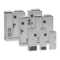
Eaton HCU2/HCUn active harmonic
lter installation manual
EATON www.eaton.com
Pre-commissioning
This section provides information for preparation of the active filter
for commissioning. Before applying power, read and understand this
information thoroughly.
Instruments required for commissioning
•
Voltmeter or multimeter
•
Clamp-on ammeter
•
Megohmmeter
Pre-energizing procedure
WARNING
HAZARD OF ELECTRIC SHOCK, EXPLOSION, OR ARC FLASH.
• APPLY APPROPRIATE PERSONAL PROTECTIVE EQUIPMENT (PPE) AND
FOLLOW SAFE ELECTRICAL WORK PRACTICES. SEE NFPA 70E IN THE
USA, CSA Z462, OR APPLICABLE LOCAL STANDARDS
• THIS EQUIPMENT MUST BE INSTALLED AND SERVICED ONLY BY
QUALIFIED ELECTRICAL PERSONNEL
• DO NOT EXCEED THE DEVICE’S RATINGS FOR MAXIMUM LIMITS
• GROUND EQUIPMENT USING THE GROUND CONNECTING POINT
PROVIDED BEFORE TURNING ON ANY POWER SUPPLYING THIS
DEVICE
• TURN OFF ALL POWER SUPPLYING THIS DEVICE AND THE
EQUIPMENT IN WHICH IT IS INSTALLED BEFORE WORKING ON THE
DEVICE OR EQUIPMENT
• AFTER REMOVING POWER, WAIT FOR 15 MINUTES TO ALLOW THE
CAPACITORS TO DISCHARGE PRIOR TO OPENING THE DOORS OR
REMOVING COVERS
• ALWAYS USE A PROPERLY RATED VOLTAGE SENSING DEVICE TO
CONFIRM POWER IS OFF
• REPLACE ALL DEVICES, DOORS, AND COVERS BEFORE TURNING ON
POWER TO THIS EQUIPMENT
• CAREFULLY INSPECT THE INTERIOR FOR TOOLS LEFT BEHIND BEFORE
CLOSING AND SEALING THE DOOR
FAILURE TO FOLLOW THESE INSTRUCTIONS WILL RESULT IN DEATH OR
SERIOUS INJURY.
Installation inspection
Inspect all connections for both power and control wiring. Ensure
that the correct termination points have been made for each wire.
Ensure that all connections are firmly tightened prior to start-up.
Pre-commissioning checklist
Prior to commissioning the active filter system, the following items
must be completed:
•
Electrical connections have been made in accordance with
local codes
•
Main CTs are installed to measure the current of the system to
be corrected
•
The secondary wiring of the main CTs have been connected to
the CT board of the active filter
•
If it is a parallel active filter system, CT wiring and parallel
communications wiring have been installed between the CT
boards of each unit
•
All drives, harmonic generating loads, downstream of the main
CTs must have the recommended minimum 3% line reactor or
DC choke installed (required for optimum performance when
harmonic mode is intended)
•
There are no un-isolated capacitors, such as power factor
correction capacitors downstream of the main CTs. (required
when harmonic mode is intended to operate)
•
At least 50% of the anticipated load should be available during the
commissioning procedure. To fully test the system integration, all
loads supported by the active filter system should be available for
operation. The total output current required for the system must
be at least 10% of the unit’s nameplate rating. For example, a
300A unit will need a minimum of 30 A total output current
•
If backup generation is connected to the active filter, the
system should also be tested with the generator supporting the
connected loads
The Field Service Engineer will need to know the following
information to commission the active filter:
•
Installation location of the main CTs in relationship to the active
filter (load or grid)
•
The ratio of the main CTs installed
•
The phase on which each CT is installed
•
Intended mode of operation (Harmonic, Power Factor,
Load Balancing)
Commissioning procedures
Refer to the User Manual for commissioning procedures.
The User Manual is available as a download from our website.
 Loading...