I.B. 2C12060H08
For more information visit: www.EatonElectrical.com
Instruction Book
Page 24
Effective: May 2006
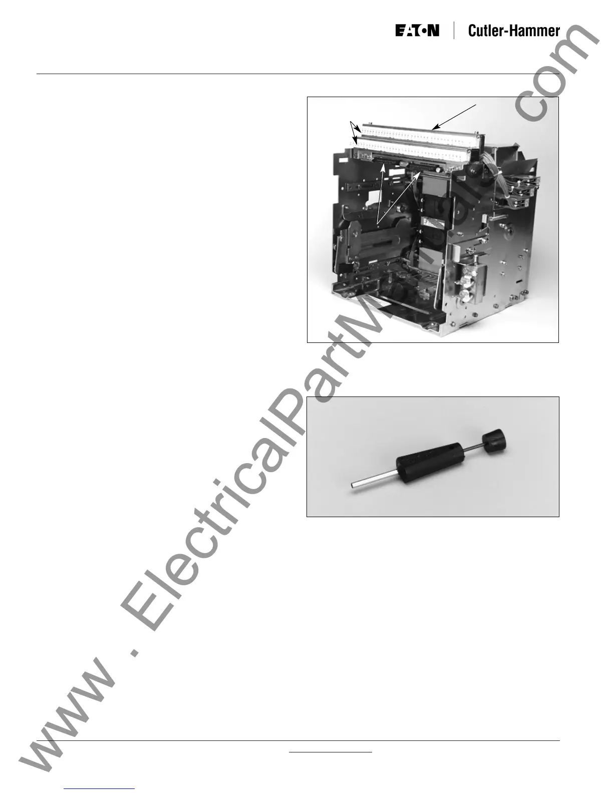
Drawout type circuit breakers: Compatible secondary
plug-in connectors are mounted on the top front portion
of the drawout cassette (Figure 3-24). These connec-
tors match and plug into the circuit breaker mounted
connectors. Contact points are wired from the cas-
sette’s plug-in connectors to cassette mounted terminal
blocks. The terminal blocks are also mounted on the
top front portion of the cassette. The secondary termi-
nals have finger-proof hinged covers with small holes for
probe testing.
Fixed type circuit breakers: There are two secondary
connection options:
(1) Without Terminal Block
(2) With Terminal Block
1. Without Terminal Block - If a terminal block for
customer use is not required, the circuit breaker is
supplied with both plug-in connectors (male and
female) just described in the two previous para-
graphs. The plug-in connectors are joined and
attached to the top portion of the circuit breaker.
The customer can plug secondary wiring with crimp-
on connectors into back of the plug-in connectors;
subsequently the connections to the circuit breaker
can be quickly joined or separated as required.
2. With Terminal Block - For those customers pre-
ferring to wire to a terminal block, terminal blocks
with finger-proof hinged covers are added to the
secondary configuration just described for a fixed
circuit breaker “without a terminal block.” The termi-
nal blocks are wired to the plug-in connectors and
also permanently attached to the upper rear portion
of the circuit breaker (Figures 3-2 and 3-4).
A standard tool is available from the plug-in connector
manufacturer (AMP) to facilitate the removal of sec-
ondary wiring from a plug-in connector, or contact
Cutler-Hammer for assistance (Figure 3-25). The con-
nector halves must be separated to use this tool.
3-7.1 CONNECTION DIAGRAMS
The connection diagrams for all Magnum circuit break-
ers using Digitrip RMS trip units are shown in Figures
3-26 through 3-46.
Figure 3-25 AMP Secondary Wiring Removal Tool
Figure 3-24 Typical Cassette Mounted Secondary
Wiring
Terminal Blocks
Closed Hinged Covers
with Testing Holes
Plug-in
Connectors
 Loading...