3-2 BASIC CIRCUIT BREAKER ASSEMBLY
All Magnum circuit breakers use a rigid frame housing
construction of engineered thermoset composite resins.
This construction provides high strength structural prop-
erties, excellent dielectric characteristics and resistance
to arc tracking.
The 3-piece construction approach provides support
while isolating and insulating power conductors (Figure
3-6):
(1) A 2-piece engineered thermoset composite resin
case encloses current paths and arc chambers. The
chambers act to channel arc gases up and out of the cir-
cuit breaker during interruption.
(2) The operating mechanism sits on the front of the
case and is electrically isolated and insulated from cur-
rent contact structures. It is covered by an insulating
front cover.
3-3 POLE UNITS
A current carrying pole unit is individually enclosed and
rigidly supported by the case. The individual chambers
provide for pole unit isolation and insulation from one
another. Each pole unit has one primary contact
assembly, which consists of a moving portion and a
fixed portion. The exact design configuration depends
upon the breaker’s frame size. Circuit breakers with
frame sizes of 4000 amperes and higher use two pole
units and arc chute assemblies connected mechanically
and electrically in parallel to form one phase.
I.B. 2C12060H08
For more information visit: www.EatonElectrical.com
Instruction Book
Page 15
Effective: May 2006
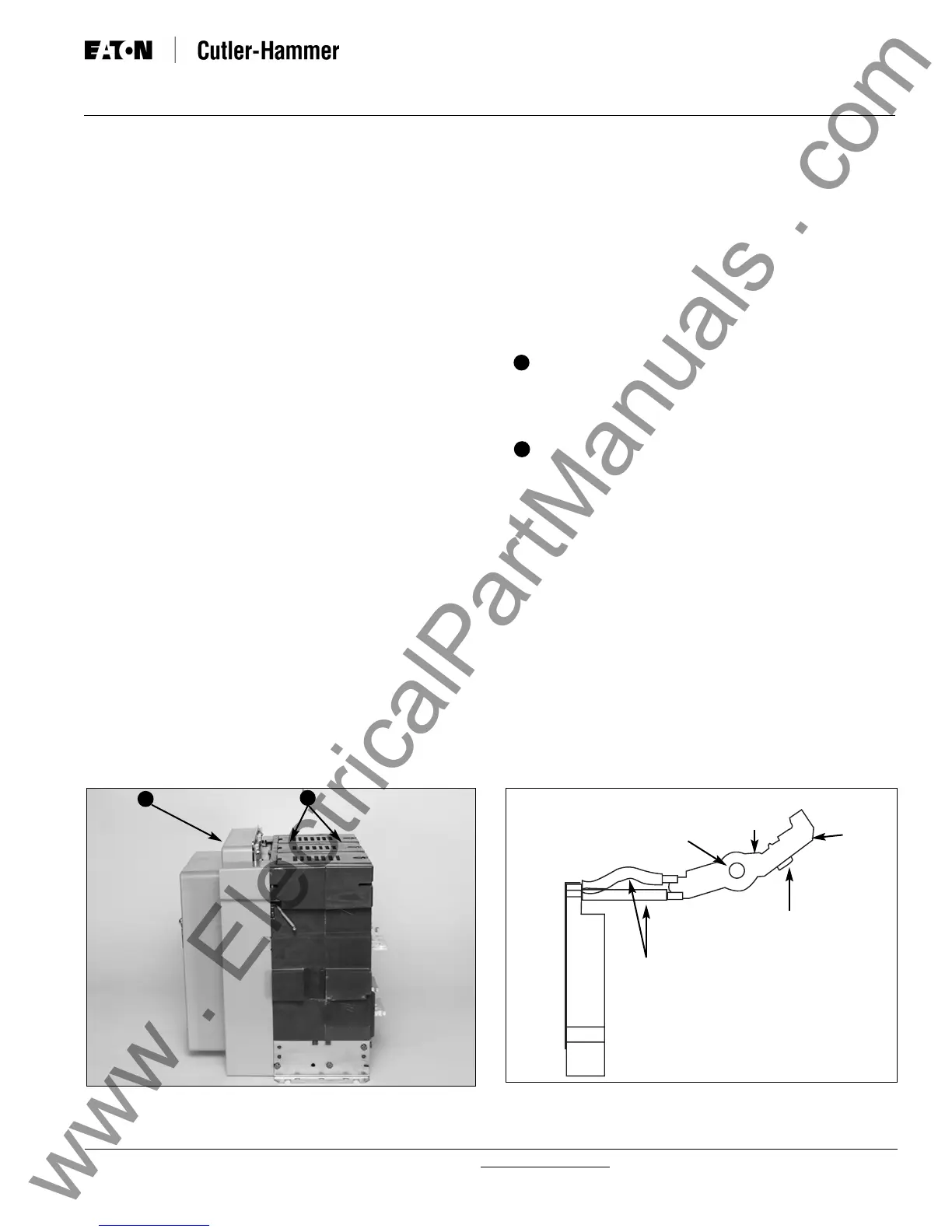
Figure 3-6 Typical Magnum Construction (Right Side
View)
2
1
3-1.1 MDSL APPLICATION/OPERATION
MDSL circuit breakers are intended for applications
requiring the overload protection and switching functions
of air circuit breakers on systems whose available fault
currents (1) exceed the interrupting ratings of the circuit
breakers alone and/or (2) exceed the withstand and
interrupting ratings of downstream circuit components.
The 800 through 2000 amp frame MDSL circuit break-
ers have integrally mounted limiters on the drawout
breaker element. On overloads and faults within the cir-
cuit breaker interrupting rating, the circuit breaker pro-
tects the limiters. On higher fault currents exceeding
the circuit breaker rating, the limiters protect the circuit
breaker.
Interlock arrangements trip the circuit breaker whenever
any limiter blows. The circuit breaker cannot be
reclosed on a live source unless there are three
unblown limiters on the circuit. The blown fuse indica-
tor, located on the front of the circuit breaker, provides a
visual indication when a current limiter in any phase has
interrupted a short circuit. In addition, a blown limiter
sensing circuit insures that a circuit breaker will be
tripped when any current limiter has blown, preventing
single phasing.
The MDSL circuit breaker must be completely with-
drawn from its compartment onto the compartment’s
extension rails, thus assuring complete isolation, before
the integral current limiters are accessible.
Additional information concerning current limiter ratings,
limiter replacement and blown fuse operation is provid-
ed later in this chapter.
2
1
Figure 3-7 Features of Magnum Moving Conductor
Assembly
Pivot
Point
Single Contact
Finger
Moving
Arcing
Contact
Area
(Toe)
Moving Main Contact
Conductive Pad
(Heel)
Dual
Flexible
Connections
(Case)(Front Cover)
 Loading...