Do you have a question about the Eaton PKZM0-0,16 and is the answer not in the manual?
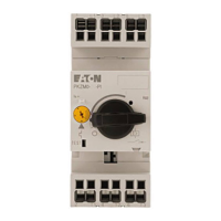
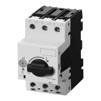
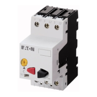
The device described in this manual is a Motor-protective circuit-breaker, specifically the PKZM0-.../XTPR...BC1NL and PKZM0-...-T/XTPT...BC1NL series. Its primary function is the overload monitoring of standard and Ex e motors, providing protection against thermal overheating.
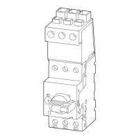
The PKZM0-.../XTPR...BC1NL and PKZM0-...-T/XTPT...BC1NL are three-pole electromechanical motor-protective circuit-breakers equipped with bimetallic releases for overload monitoring. When an overload occurs, the circuit-breaker disconnects all phases from the main circuit, directly switching off the power flow to the monitored motor.
A key feature of these circuit-breakers is their temperature compensation. The deflection of the bimetallic releases is influenced by both the current flow and the ambient air temperature. To ensure accurate tripping, the device automatically compensates for ambient air temperature within a range of -5 to +40 °C using an additional current-free bimetallic release. This continuous correction maintains the tripping range's accuracy.
The circuit-breakers are also phase sensitive. The deflecting action of all three bimetallic releases is directed towards a tripping bridge that activates a quick-break switch when a limit value is reached. Simultaneously, all three bimetallic releases shift a differential bridge. If one bimetallic release's action path is reduced due to a phase loss, the differential bridge is retarded, and the distance is converted into an additional tripping distance, leading to an early trip. This phase sensitivity is crucial for protecting motors from damage due to unbalanced loads or phase loss. For monitoring AC or DC motors, current must flow across all three current paths to prevent premature tripping.
The motor-protective circuit-breakers are available in 15 different types, capable of monitoring motors with a rated current ranging from 0.1 to 32 A. The specific current range for each type is set via a current dial on the device. For example, the PKZM0-0,16/XTPRP16BC1NL covers 0.1-0.16 A, while the PKZM0-32/XTPR032BC1NL covers 26-32 A (open) or 26-30 A (enclosed).
The devices are built according to IEC/EN 60947 regulations for low-voltage switchgear. They also comply with the 94/9/EG (ATEX 95) and 2014/34/EU (ATEX) directives for the protection of Ex e motors, making them suitable for use in potentially explosive atmospheres. Additionally, they can be used for motor protection in accordance with EN 60079 in Zones 21 and 22 (areas with flammable dust).
The short-circuit breaking capacity varies depending on the voltage and coordination type. For instance, at 230 V, many types offer 150 kA breaking capacity with coordination type "1". At higher voltages like 690 V, the breaking capacity can be 50 kA. The wiring of the motor feeder must adhere to IEC/EN 60947-1, Table 9.
For functional safety, the devices are classified under EN IEC 61508/EN IEC 62061 and EN ISO 13849. In continuous demand operation (> 1/year), they achieve SIL 1/SIL CL 1 with a Safe Failure Fraction (SFF) of 25% and a Frequency of Dangerous Failure per Hour (PFHD) of 20.06 x 10^-9. In low demand operation (≤ 1/year), they also achieve SIL 1/SIL CL 1 with a Safe Failure Fraction (SFF) of 25%. The Average Probability of a Dangerous Failure (PFDavg) is 0.879 x 10^-4 for a 12-month test interval and 2.63 x 10^-4 for a 36-month test interval. According to EN ISO 13849, the devices are classified as Category 1 with a Performance Level (PL c). The Mean Time to a Dangerous Failure (MTTFD) is 5689 years, limited to 100 years, and Diagnostic Coverage (DC) is 0%.
The maximum conductor cross-sections for motor cables are specified: 1-6 mm² (1.7 Nm / 15 lb-in) and 1-4 mm² (1.7 Nm / 15 lb-in) for general wiring, and AWG18-8 Cu 75 °C (1.8 Nm / 16 lb-in) for UL-approved wiring.
The motor-protective circuit-breakers are designed for manual operation. After an overload trip, the bimetallic releases must cool down before the device can be reset. Resetting can only be performed locally at the installation.
The current setting is adjusted via a current dial on the front of the device, allowing precise matching to the motor's rated current.
A testing element is integrated into the device to allow for verification of its proper functioning. By actuating this test release with a screwdriver while the circuit-breaker is active, the device will trip, opening all main contacts and removing the output lines from the voltage source. This feature is particularly useful during commissioning to ensure the circuit-breaker operates correctly.
The manual includes detailed tripping characteristics (Auslösekennlinien) for each specific type of circuit-breaker, showing the tripping time (t) in seconds or minutes versus the multiple of the set current (x Ir) for both 3-phase and 2-phase operation. These curves are essential for understanding the device's behavior under different overload conditions and for proper system coordination.
For safety-related parts of control systems, it is noted that if tripping occurs via thermal or magnetic release, or manual actuation, with a frequency of up to 1890 times per year, the devices must be replaced after 10 years according to ISO 13849. Users must also check if relevant regulations (e.g., EN 50156) require shorter test intervals for functional safety.
| Brand | Eaton |
|---|---|
| Model | PKZM0-0, 16 |
| Category | Circuit breakers |
| Language | English |