7
2 PXR user interface
PXR TRIP UNITS FOR POWER DEFENSE MOLDED CASE CIRCUIT BREAKERS MN012007EN March 2019 www.eaton.com
2.1.5 Battery
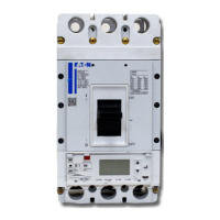
For PXR units, which have cause-of-trip indicators, within the trip unit is a small tray that
holds the battery. The battery supports the cause-of-trip indicators for 20 days when the
trip unit is not powered. The battery plays no part in the protection functions of the trip
system. On the initial installation of the circuit breaker, remove and discard the insulating
tab to enable the battery. This battery is a standard CR type “coin-cell”, for replacement use:
CR1216. The battery also holds the power for the real time clock chip for time and date infor-
mation. After replacing the battery, the time and date should be reprogrammed.
The “RESET” button can be pressed and held for two seconds to test the battery. If OK,
the “LONG” LED will illuminate green, if the battery should be replaced it will illuminate
yellow. For PXR 20D and PXR 25 the battery status is also indicated in the lower right
corner of the display.
2.1.6 High load indicator
On the PXR 20D and PXR 25, the indicator labeled “Alarm1/Alarm2” (high-load indicator) is
illuminated yellow based on the configured load setting. The LED will be solid when above
the high load warning (Alarm1) pickup, and the LED will blink when above the high load
alarm (Alarm2) pickup. Note that high load alarm (Alarm2) (blink) takes precedence over high
load warning (Alarm1) (solid).
On the PXR 20, the indicator labeled “85%Ir/105%Ir” (high-load indicator) is illuminated
yellow based on fixed setting. The LED will be solid when above the the 85% of Ir fixed
load setting, and the LED will blink when above the 105% of Ir fixed load setting. Note that
fixed laod setting 105% Ir (blink) takes precedence over fixed load setting 85% Ir (solid).
2.1.7 Maintenance Mode switch
When supplied, the PXR trip unit incorporates the Arc Flash Reduction Maintenance
System™ (ARMS). The switch is labeled “Maintenance Mode” and has two positions
labeled “OFF/Remote” and “ON”. A blue light next to the Maintenance Mode switch illumi-
nates when the ARMS protection is enabled.
•
“ON” – ARMS is enabled locally and cannot be disabled remotely
•
“OFF/Remote” – ARMS is OFF, or can be remotely controlled by a dry contact, communi-
cations or PXPM. See Section 3.6: Maintenance Mode protection for complete details
2.1.8 Push to trip
A red button on the front of the trip unit or circuit breaker provides a mechanical means of
tripping the circuit breaker. Use a small tool to depress it and trip the breaker mechanism.
2.1.9 Tamper proof cover
A clear plastic cover allows the settings to be viewed but not changed. Controlling physical
access is a key element in your comprehensive security policy. Unauthorized access to
change settings is prevented by insertion of a standard sealing wire through the security
holes in order to meet applicable tamper-proof requirements.
2.1.10 Password security
Protecting your system from cyber security threats is very important. In addition to the
tamper-proof cover, PXR trip units have a four-digit password used to secure certain settings
and to enable secondary injection testing. To change a setting, which is not set by a physical
switch, will require you to enter the four-digit password. Authorization to make changes will
timeout after 10 seconds of inactivity. Password security is also enforced when using the
display, PXPM software and when another device attempts a change via a communication
network.
Changing the factory default password is a key element of a comprehensive cyber security
policy. From the factory the default is ‘0-0-0-0’. Upon installation of the PXR, the password
should be changed (under the settings menu) and only made available to those individuals
who require it.

 Loading...


