Eaton SM87BG/PB Call Points
The Eaton SM87BG/PB series comprises robust manual fire alarm and emergency shutdown call points designed for demanding industrial and marine environments. These units are easy to install and maintain, offering a choice of either stainless steel or alloy enclosures. They are suitable for both offshore and onshore industries.
Function Description
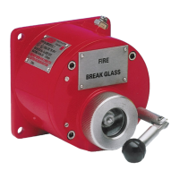
The SM87BG/PB call points are designed to initiate an alarm or emergency shutdown signal upon manual activation. The SM87BG model features a "Break Glass" mechanism, requiring the user to break a glass pane to access and activate the internal button. The SM87PB model, on the other hand, utilizes a "Push Button" mechanism, often protected by a lift flap, allowing for direct activation. Both models are equipped with a red high-intensity LED for alarm indication, powered by current protection and limited to 20mA.
The SM87BG (Break Glass) unit operates by breaking the glass element in the front cover using the hammer attached to the unit. If a lift flap is present, it needs to be raised first to gain access to the glass element. Once the glass is broken, the internal button can be pressed to activate the alarm. To reset the SM87BG, a kit containing O-rings and new glass is provided. The user must unscrew and remove the circular bezel, remove the original O-rings and glass, clean the grooves, fit the smaller O-ring into the groove on the cover, and then the larger O-ring into the groove on the bezel. The new glass element is then placed into position on the cover, and the bezel is reassembled over the top of the glass element. The glass element stays central on the cover by pressing down with the thumb through the hole in the center of the bezel. Carefully, the glass element is depressed to depress the plunger until the glass is in full contact with the cover O-ring, ensuring an even gap around the glass. The bezel is then screwed down until the bottom of the bezel is tightened against the cover.
The SM87PB (Push Button) unit operates by lifting the flap on the front of the cover, then depressing the steel actuator underneath. Depending on the unit type ordered, the actuator will either remain in its depressed position (latching versions) or return to its original position (momentary versions). To reset a latching SM87PB unit, a key is inserted into the slot in the front face of the actuator. The key is turned slightly to locate it in the actuator and pulled back to the initial position. The key can then be removed, and the flap lowered. For the SM87PB Turn and Push model, the unit is operated by lifting the flap on the front cover, then turning the actuator anti-clockwise 90° and depressing it. The actuator will remain in its depressed position. To reset, the actuator is turned anti-clockwise 90° and the flap can then be lowered.
Important Technical Specifications
The units are available with the following options and features:
- Lift flap: Provides protection against accidental activation.
- Duty label: Clearly indicates the unit's function.
- Tag label: For custom identification.
- Earth continuity via internal/external earth studs: Ensures proper grounding.
- LED: Red high-intensity LED for alarm indication (current limited to 20mA).
- End of Line and Series resistors and diodes: For circuit configuration.
- Two switches (four poles maximum): Allows for multiple circuit connections.
- M20 or M25 gland entries: Available in a range of positions, with a maximum of four.
- Optional momentary or latching with key reset actions: For specific operational requirements.
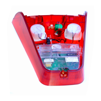
Cable Termination:
- Removable cover assembly for easier installation.
- Four M6 screws (5.0mm A/F hexagon key) secure the cover.
- Internal cable termination in accordance with specific installation drawings and MEDC recommendations.
- Correctly listed or certified cable glands are required, and the assembly must be shrouded and correctly earthed.
- All cable glands should be of an equivalent NEMA/IP rating to that of the call point and integrated with the unit such that the rating is maintained.
- Internal earth terminal, where fitted, must be used for the equipment grounding conductor and the external terminal for a supplementary bonding connection.
- Once termination is complete, carefully push the cover assembly back onto the base, avoiding damage to the mating surfaces. Ensure that the retaining strap is not trapped between the mating surfaces and that the O-ring is correctly seated in its groove. The microswitch strap and wires are clear of the microswitch actuator and operating mechanism. Replace the 4 off M6 screws (5.0mm A/F hexagon key) into the holes in the cover assembly and tighten evenly. The maximum gap of 0.15mm must be maintained between the cover and the base once assembled.
Certification/Approvals:
- IECEx units: Certified to IEC 60079-0, IEC 60079-1, and IEC 60079-31.
- Ex d IIC T6 (-55 °C to +55 °C) Gb
- Ex tb IIIC T85 °C (-55 °C to +55 °C) Db IP66/IP67
- ATEX units: Certified to EN 60079-0, EN 60079-1, and EN 60079-31.
- Ex d IIC T6 (-55 °C to +55 °C) Gb
- Ex tb IIIC T85 °C (-55 °C to +55 °C) Db IP66/IP67
- DNV approved (SM87PB only): Approved according to IEC60945: Marine navigation and radio communication equipment and systems.
- Compass safe distance: 5m.
Functional Safety (SM87PB Pushbutton):
- Designed for use in potentially explosive atmospheres and harsh environmental conditions.
- The marine grade alloy or stainless steel enclosures are for use on-shore or offshore, where light weight combined with corrosion resistance and strength is required.
- The function of the call point is to raise an alarm manually once the condition of a fire or emergency condition exists, by pushing the button.
- The safety function of the SM87PB Call Point is to raise the alarm when the Button is pressed.
- Under normal operating conditions, the SM87PB Push Button will raise an alarm upon operating the switch via pushing the button.
- Under fault conditions, the failure mode of the Push Button is a failure to raise an alarm.
- PFH (Probability of Dangerous Failure per Hour): 3.43E-08 (Low Demand Mode), 3.43E-08 (High Demand Mode).
- SFF (Safe Failure Fraction): 79.7%.
- SIL Capability: SIL 2 (Low Demand), SIL 2 (High Demand).
- Route 1H: Hardware safety integrity compliance and systematic safety integrity compliance.
- SC2: Systematic Capability.
Usage Features
- Robust Construction: The units are designed for use in arduous and demanding environmental conditions, making them suitable for a wide range of industrial applications.
- Easy Installation: The removable cover assembly simplifies the installation process, allowing for easier access to internal components and cable termination.
- Versatile Mounting: Units can be mounted vertically, horizontally, or angled, providing flexibility in installation.
- Multiple Gland Entries: M20 or M25 gland entries in various positions (up to four) accommodate different cabling requirements.
- Clear Indication: The red high-intensity LED provides clear visual confirmation of alarm activation.
- Optional Reset Mechanisms: Choice of momentary or latching with key reset actions allows for customization based on operational needs.
- Corrosion Resistance: Available in stainless steel or alloy enclosures for enhanced durability in harsh environments.
Maintenance Features
- Regular Visual Inspections: During the working life of the unit, it should require little or no maintenance. However, if abnormal or unusual environmental conditions occur due to plant damage or accident, then visual inspection is recommended. If the unit requires cleaning, it should only be cleaned with a damp cloth to avoid electro-static charge build-up.
- Spare Parts Availability: If a unit should occur damage, the unit can be repaired by MEDC. All parts of the unit are replaceable. It is recommended to purchase a significant quantity of units as spares to ensure availability.
- Glass Replacement (SM87BG): A specific procedure is outlined for replacing the glass element, including O-ring replacement and careful reassembly to maintain the unit's integrity.
- Actuator Reset (SM87PB): Latching versions of the SM87PB can be reset using a key, simplifying the process of returning the unit to its original state after activation.
- Functional Safety Assessment: Regular assessment of functional safety is recommended to ensure the unit continues to meet the required safety integrity levels. This includes verifying the design, installation, configuration, overall validation, maintenance, and repair procedures.
- Documentation: Users must comply with the requirements detailed in the documentation provided by the manufacturer, including the safety manual and technical manual, regarding all relevant functional safety aspects.
- Competent Personnel: All personnel involved in the installation, operation, and maintenance of the equipment should be competent.
- Regular Intervals for Checks: The unit should be tested at regular intervals to identify any malfunctions, in accordance with the safety manual.