Do you have a question about the Eaton FX6100 and is the answer not in the manual?
Explains warning symbols and definitions used throughout the manual.
Outlines general safety guidelines to be followed during operation and maintenance.
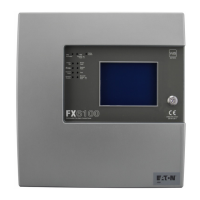
Provides an overview of the panel's features and benefits for installers and users.
Details a typical program and timetable for a panel installation project.
Covers standards and practices for system design, including BS5839 part 1.
Specifies the maximum permitted loop length and wiring considerations.
Lists various compatible equipment with order codes and dimensions.
Details compatibility requirements for sensors, call points, and sounders.
Describes the panel's user interface, configuration, and sounder control features.
Details electrical and mechanical specifications of the panel.
Describes optional features compliant with EN54 Parts 2 & 4.
Outlines allowable cable types and essential wiring requirements for loop connections.
Provides crucial guidelines and precautions for installing the fire alarm panel.
Explains how to mount the panel's backbox, either surface or recessed.
Details the process of installing power and loop cables into the backbox.
Details how to connect external wiring, including mains supply requirements.
Explains how panels can be networked together to form a single system.
Describes the panel's output terminals for sounders and other routing equipment.
Outlines daily, weekly, and quarterly inspection and testing procedures.
Explains the walk test mode for testing detectors and call points during commissioning.
Covers configuration aspects like sounder db level checks and detector LED flashing.
Details how to use PC software for downloading configuration data to panels.
Provides voltage readings and fault conditions for troubleshooting panel issues.
Describes the PC software interface for device configuration and programming.
Explains how different input states (Fire, Fault, etc.) are programmed.
Allows defining zones or addresses for isolation upon device activation.
Details configuration options for device outputs, including delays.
Details coincidence detection for assigning zones to activate panel outputs.
Describes the function and action for each system LED on the panel.
Introduces the touch screen display as the primary interface for panel operations.
Explains the multi-function touch screen display and its event display capabilities.
Details how to navigate and operate the panel functions via the touch screen interface.
Guides through activating the auto-learn function for system configuration.
Explains how to load configuration data (CDR) from a laptop to the panel.
Describes how to download configuration data (CDR) from the panel to a laptop.
Details functions available without an access code for reviewing system status.
Explains how to initiate an evacuation sequence from the panel.
Describes the procedure to silence active sounders on the panel.
Explains how to mute the panel's internal buzzer.
Guides on how to reset the panel after an alarm or fault condition.
Describes how pre-alarm conditions are indicated and what they might signify.
Explains how to view and manage devices that have been disabled in the system.
Details how to view and clear fault conditions reported by the panel.
Accesses options for enabling or disabling various panel functions.
Covers enabling/disabling specific addresses, zones, or I/O units.
Describes the printing function, noting it may not be available.
Explains how to perform a lamp test on the panel's indicators.
Details the procedure for conducting the weekly system test via the touch screen.
Guides on how to access and view the panel's event log.
Explains how to scan the loop to identify device locations and configuration changes.
Describes the process for replacing an existing device without losing its programming.
Allows individual testing of devices on the loop at a higher access level.
Enables testing of specific zones within the system.
Allows testing sounder outputs with specific pulse patterns.
Controls the global flashing of device LEDs for communication confirmation.
Details the procedure for performing a walk test by a single engineer.
Explains how to delete all log entries from the panel's memory.
Displays detailed system information, including software versions and device counts.
Allows uploading a custom logo from a PC to be displayed on the panel.
Shows analogue input levels for devices and allows navigation by address.
Sets the unique identification number for a panel within a network.
Configures the total number of panels connected in a networked system.
Option to set the panel to display a screen saver or cover.
Configures the panel for specific Italian language and operational modes.
Allows programming of I/O modules and sounders, including delay parameters.
Configures panel output behavior for I/O and sounder modules.
Details programming options for auxiliary boards connected to I/O and sounder modules.
Configures alarm verification settings for I/O and sounder modules.
Allows adjustment of global sounder volume and tone settings.
Provides the interface to set the panel's current date and time.
Enables changing the text labels associated with specific zones on the panel.
Allows modification of text labels for devices, zones, and the panel itself.
Specifically allows changing the text displayed on the main panel interface.
Describes how to add devices to specific zones or reconfigure existing zone assignments.
Guides the user through changing the system's access passcode for security.
Explains the process for adding new zones to the system configuration.
Details the procedure for removing zones from the panel's configuration.
Guides on adding new devices to the loop and confirming their configuration.
Explains how to remove a device from the system and its configuration.
Allows setting the class (e.g., Thermal A1R) for heat detectors.
Configures how messages are broadcast across a networked system.
Allows selection of the display language for the panel interface.
Configures delay settings for day/night operational modes.
Details the password system for restricting access to sensitive menus.
Provides a schematic diagram of the overall system wiring connections.
Details the wiring connections for the FXN720 detector base.
Describes the wiring for FXN501/FXN503 addressable call points.
Details the wiring connections for CAS380/CASBB384 base sounders.
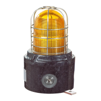
Describes the wiring for the CAB382 loop-powered beacon.
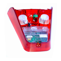
Details the wiring for FXN538LPS/FXN539LPS wall sounders.
Describes wiring for IP66 rated FXN538LPSWP/FXN539LPSWP wall sounders.
Details wiring for the CASBB394 Base Sounder VAD.
Details wiring for the CASB393 Wall Sounder VAD.
Details wiring for the IP66 CASB393WP Wall Sounder VAD.
Describes wiring for the CIO351 series 3-way input/output units.
Details wiring for the CMIO353 1-channel mains-rated I/O unit.
Describes wiring for the CZMU352 addressable zone monitor unit.
Details wiring for the CZMU352-IS intrinsically safe zone monitor unit.
Describes wiring for the MSU840 shop monitor unit.
Explains wiring for the CSI350 spur isolator, critical for addressability.
Details wiring for the CSC354CPR 4-way sounder controller.
Describes wiring for 4-20mA interface modules.
Details wiring for the JIU872 micro zone monitor module.
Describes wiring for the MJIM micro input module.
Details wiring for MJOM series micro output modules.
| Communication | Ethernet (Optional) |
|---|---|
| Input Voltage | 120/230V AC (auto-ranging) |
| Frequency | 50/60 Hz |
| Battery Type | Sealed lead-acid (maintenance-free) |
| Operating Temperature | 0°C to 40°C (32°F to 104°F) |
| Humidity | 0% to 95% relative humidity (non-condensing) |
| Certifications | UL |