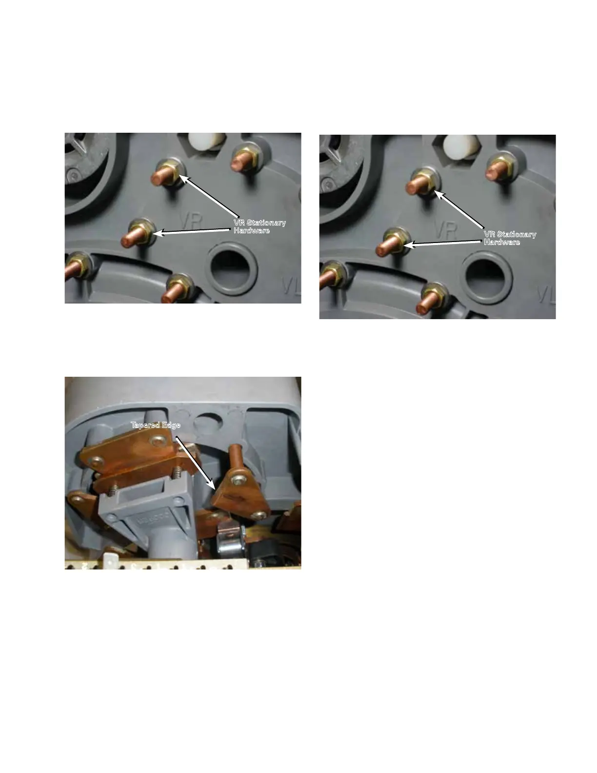
3. To remove a VR Reversing Stationary Contact use a
9/16" socket and ratchet to loosen and remove both the
nuts and flat washers from each of the contact studs.
See Figure 98.
4. Remove the VR reversing stationary contact from the
contact assembly panel. See Figure 106.
5. Install the new VR reversing stationary contact into
the mounting holes in the contact assembly board.
Make sure when installing the contact that the leading
tapered edge is positioned toward the reversing neutral
stationary contact. If the tapered edge is facing in the
wrong direction, the stationary VL contact is being
used. See Figure 99.
6. Place a flat washer and nut on each stud. Use a 9/16"
socket and ratchet to tighten the nuts on each contact
stud. Using a torque wrench tighten the nuts to a
torque of 80–90 lb-ins (9.0–10.2 Nm). See Figures 100.
7. Once the work has been completed, place the tap-
changer in the neutral position.
Figure 98. Reassembling hardware.
VR Stationary
Hardware
Figure 100. Removing hardware.
VR Stationary
Hardware
Figure 99. VR reversing stationary contact removal
Tapered Edge
37
QD5 QUIK-DRIVE TAP-CHANGER INSTALLATION AND MAINTENANCE INSTRUCTIONS MN225012EN March 2016
 Loading...


