EasyManuals Logo

Eaton Tandem ELF Current-Limiting Dropout Fuse Installation And Adjustment Instructions

Eaton Tandem ELF Current-Limiting Dropout Fuse
16 pages
To Next Page IconTo Next Page
To Previous Page IconTo Previous Page
Page #13 background imageLoading...
Page #13 background image
9KA369R, KA542R, AND KA57WE AUXILIARY SWITCH KIT INSTALLATION AND ADJUSTMENT INSTRUCTIONS MN280031EN
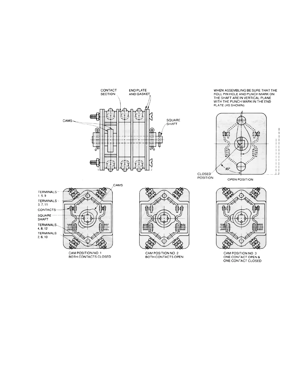
7. Replace the cams in one of the positions shown in
Figure 15.
8. Reposition and fasten the switch sections to the
housing base plate.
9. Replace the collar and cotter pin on the shaft.
10. Remount the assembled switch on the recloser head,
making sure that the pin in the square shaft engages
the notch in the switch operating shaft in the head
casting.
Figure 15. Auxiliary switch cam positions.

Other manuals for Eaton Tandem ELF Current-Limiting Dropout Fuse

Questions and Answers:

Question and Answer IconNeed help?

Do you have a question about the Eaton Tandem ELF Current-Limiting Dropout Fuse and is the answer not in the manual?

Eaton Tandem ELF Current-Limiting Dropout Fuse Specifications

General IconGeneral
BrandEaton
ModelTandem ELF Current-Limiting Dropout Fuse
CategoryCables and connectors
LanguageEnglish

Related product manuals