Chapter 2.2.1. – 3
EATON CORPORATION xxxxx+xxxx-xxxxEN
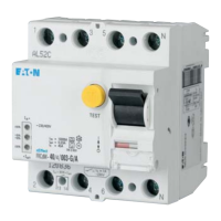
Residual Current Devices
Specifications | Residual Current Devices FRCdM
Description
Accessories:
Auxiliary switch for subsequent installation to the left Z-HK 248432
Tripping signal contact for subsequent installation to the right Z-NHK 248434
Automatic restarting device Z-FW/LP 248296
Z-FW-LPD 265244
Remote control Z-FW-MO 284730
Pre-mounted sets Z-FW-LP/MO 290171
Z-FW-LPD/MO 290172
Remote testing module Z-FW/003 248298
Z-FW/010 248299
Z-FW/030 248300
Sealing cover set Z-RC/AK-4TE 101062
Switching interlock IS/SPE-1TE 101911
• Residual current devices
• Shape compatible with and suitable for standard busbar connec-
tion to other devices of the xEffect-series
• Twin-purpose terminal (lift/open-mouthed) above and below
• Busbar positioning optionally above or below
• Free terminal space despite installed busbar
• Universal tripping signal switch, also suitable for FAZ, FRBmM-1N
can be mounted subsequently
• Auxiliary switch Z-HK can be mounted subsequently
• Contact position indicator red - green
• Tripping indicator white - blue
• Additional Safety
- possibility to seal
- possibility to lock in ON and OFF position
• Delayed types suitable for being used with standard fluorescent
tubes with or without electronical ballast (30mA-RCD: 30 units per
phase conductor, 100mA-RCD: 90 units per phase conductor).
Notes: Depending of the fluorescent lamp ballast manufacturer
partly more possible. Symmetrical allocation of the fluorescent
lamp ballasts on all phases favourably. Shifting references of the
fluorescent lamp ballast manufacturer consider.
• The device functions irrespective of the position of installation
• Tripping is line voltage-independent. Consequently, the RCD is suit-
able for “fault current/residual current protection” and “additional
protection” within the meaning of the applicable installation rules.
• Mains connection at either side
• The 4-pole device can also be used for 3-pole connection:
See connection possibilities.
• The 4-pole device can also be used for 2-pole connection:
See connection possibilities.
• The test key “T” must be pressed every year. The system operator
must be informed of this obligation and his responsibility in a way
that can be proven. The yearly test interval is only valid for residen-
tial and similar applications. Under all other conditions (e.g. damp -
ly or dusty environment), it's recommended to test in shorter inter-
vals (e.g. monthly). A test is further needed if red and yellow LED
are on together.
• Pressing the test key “T” serves the only purpose of function test-
ing the residual current device (RCD). This test does not make
earthing resistance measurement (R
E
), or proper checking of the
earth conductor condition redundant, which must be performed
separately.
• Functioning
- The green LED becomes active at 0-30% I
Δn
- The yellow LED becomes active at 30-50% I
Δn
- The red LED becomes active at >50% I
Δn
• Potential-free relay (NO contact, in parallel with the yellow LED, up
to 1 A ohmic load / 230 V~) for external prewarning function.
Bistabile, means the warning stays on also when the breaker trips,
until reset.
• Type -A: Protects against special forms of residual pulsating DC
which have have not been smoothed.
• Type -G: High reliability against unwanted tripping. Compulsory
for any circuit where personal injury or damage to property may
occur in case of unwanted tripping (ÖVE/ÖNORM E 8001-1 § 12.1.6).
• Type -G/A: Additionally protects against special forms of residual
pulsating DC which have not been smoothed.
• Type -R: To aviod unwanted tripping due to X-ray devices.
• Type -S: Selective residual current device sensitive to AC, type -S.
Compulsory for systems with surge arresters downstream of the
RCD (ÖVE/ÖNORM E 8001-1 § 12.1.5).
• Type -S/A: Additionally protects against special forms of residual
pulsating pulsating DC which have not been smoothed.
• Type -U: Suitable for speed-controlled drives with frequency con-
verters in household, trade, and industry.
Unwanted tripping is avoided thanks to a tripping characteristic
designed particularly for frequency converters.
See also explanation “Frequency Converter-Proof RCDs - What for?”.
Application according to ÖVE/ÖNORM E 8001-1 and Decision
EN 219 (1989), VDE 0100, SEV 1000.
 Loading...