Chapter 2.2.1. – 4
EATON CORPORATION xxxxx+xxxx-xxxxEN
Residual Current Devices
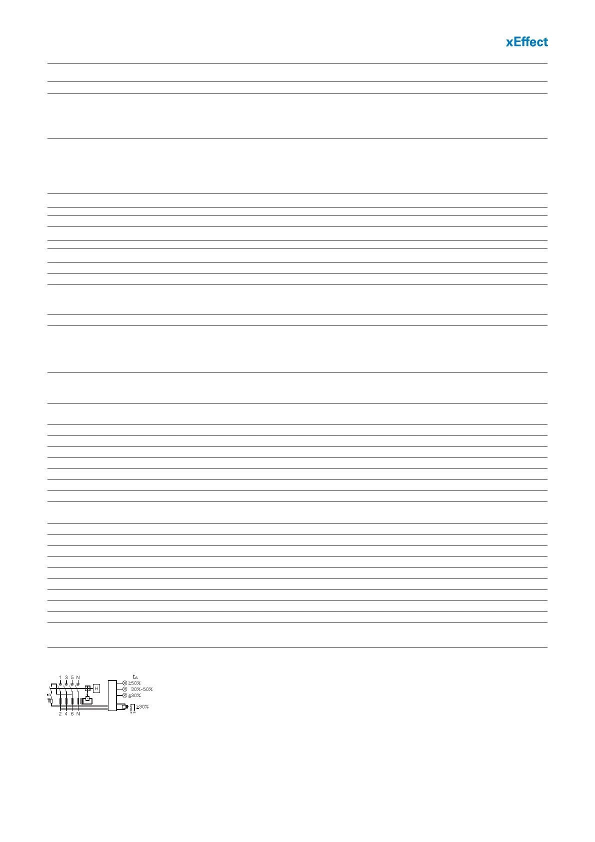
Connection diagram
4-pole
Technical Data
FRCdM
Electrical
Design according to IEC/EN 61008
Type G and G/A acc. to ÖVE E 8601
Current test marks as printed onto the device
Tripping instantaneous
Type G , R 10 ms delay
Type S 40 ms delay - with selective disconnecting function
Type U (only 30 mA) 10 ms delay
Type U (except 30 mA) 40 ms delay - with selective disconnecting function
Rated voltage U
n
240/415 V AC, 50Hz
Operation voltage electronic 50 – 264V AC
Operation voltage test circuit 196 – 264V AC
Rated tripping current I
Δn
30, 300 mA
Sensitivity AC and pulsating DC
Rated insulation voltage U
i
440 V
Rated impulse withstand voltage U
imp
4 kV (1.2/50µs)
Rated short circuit capacity I
cn
10 kA
Peak withstand current
Type G, G/A, R, U (30mA) 3 kA (8/20 µs) surge current proof
Type S/A, U (except 30mA) typ. 5 kA (8/20 µs) selective + surge current proof
Electrical isolation > 4 mm contact space
Maximum back-up fuse Short circuit and overload protection
I
n
= 16-63A 63 A gG/gL
I
n
= 80A 80 A gG/gL
I
n
= 100A 100 A gG/gL
Endurance
electrical components ≥ 4,000 operating cycles
mechanical components ≥ 20,000 operating cycles
Mechanical
Frame size 45 mm
Device height 80 mm
Device width 70 mm (4MU)
Mounting quick fastening with 2 lock-in positions on DIN rail IEC/EN 60715
Degree of protection, built-in IP40
Degree of protection in moisture-proof enclosure IP54
Upper and lower terminals open mouthed/lift terminals
Terminal protection finger and hand touch safe, BGV A3, ÖVE-EN 6
Terminal capacity 1.5 - 35 mm
2
single wire
2 x 16 mm
2
multi wire
Terminal screw M5 (Pozidriv PZ2)
Terminal capacity warning contact(s) 0.25-1.5 mm
2
(plug in terminals)
Terminal torque 2 - 2.4 Nm
Busbar thickness 0.8 - 2 mm
Tripping temperature -25°C to +40°C
Storage- and transport temperature -35°C to +60°C
Resistance to climatic conditions 25-55°C/90-95% relative humidity acc. to IEC 60068-2
Contact position indicator red / green
Tripping indicator white / blue