A
C
O
U
S
T
I
C
A
L
P
E
R
F
O
R
M
A
N
C
E
P
A
R
T
N
E
R
S
H
I
P
EASTERN ACOUSTIC WORKS
One Main Street, Whitinsville, MA 01588 • (508) 234 - 6158 • FAX (508) 234 - 8251 • BBS (800) 889-2540
EAW products are continually improved. All specifications are therefore subject to change without notice. • PUB# KF650is/C5/7/25/94 • Printed In USA
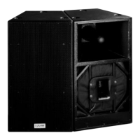
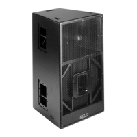
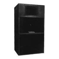
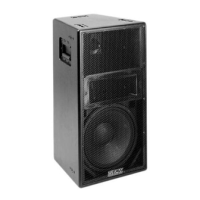
Technical Specifications KF650is
APPLICATIONS
The KF650is’ combination of compact size, high output and broad, well
defined coverage pattern make the system a good choice for applica-
tions that require even coverage of a wide area with a relatively short
throw. With optional weatherproofing, the KF650is can also be used as
part of a permanently installed outdoor system. Available in R (road)
and P (permanent) configurations.
• Performing Arts Facilities • Theaters
• Corporate AV • Touring Shows
• Churches • Clubs
• Lecture Halls • Theme Parks
Frequency Response
System Only 70 to 17 kHz ± 2.5 dB
LF Limit -3 dB 65 Hz
LF Limit -10 dB 50 Hz
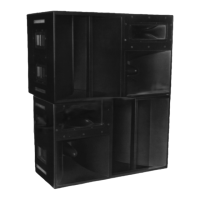
Optional Subwoofer
SB528/SB600 -3dB 31 Hz to 18 kHz
Efficiency / Axial Sensitivity
LF SPL 1w @ 1m 102 dB
MF SPL 1w @ 1m 107 dB
HF SPL 1w @ 1m 107 dB
Impedance
Nominal LF/MF/HF 8Ω/8Ω/8Ω
Power Handling
AES LF 1000 Watts
AES MF 400 Watts
AES LF 200 Watts
100 Hour Sine Wave LF 400 Watts
100 Hour Sine Wave MF 150 Watts
100 Hour Sine Wave HF 80 Watts
Maximum Output
Peak LF 132 dB SPL
Peak MF 133 dB SPL
Peak HF 130 dB SPL
Long Term LF 128 dB SPL
Long Term MF 128 dB SPL
Long Term HF 126 dB SPL
Nominal Coverage Angles (-6 dB)
Horizontal 60 degrees
Vertical 40 degrees
Additional Descriptive Data
LF Subsystem 1x15-in Wave Guide Cavity
MF Subsystem 1x10-in Cone Horn Loaded
HF Subsystem EAW CD5001 2-in Exit/Horn
CCEP
TM
Configuration MX300i-653
Powering Mode Switchable Tri-Amp or Bi-Amp
Finish Black Catalyzed Polyurethane
“P” Connectors AP6 M&F & Barrier Strip
“R” Connectors AP4 M&F, AP6 M&F
Grill Vinyl Coated Perforated Steel
Preliminary Dimensions & Weights
Height 33.25 in (845 mm)
Width 24.63 in (623 mm)
Depth 19.75 in (502 mm)
Net Weight 154 lbs (78.2 kg)
Shipping Weight 162 lbs (79.5 kg)
SPECIFICATIONS
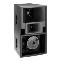
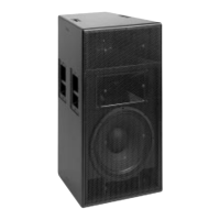
The 3-way full range loudspeaker system shall incorporate a 15-in LF
cone transducer, a 10-in midrange cone transducer and a 2-in com-
pression driver mounted to a constant directivity HF horn. The system
shall have frequency response of 70 Hz to 20 kHz ±2.5 dB; axial
sensitivity (1W@1m) of 102 dB SPL (LF), 107 dB SPL (MF), 107 dB SPL
(HF); 100 hour sine wave power handling of 400 Watts (LF), 150 Watts
(MF), 80 Watts (HF); horizontal coverage of 60° between -6 dB points;
vertical coverage of 40° between -6 dB points.
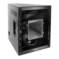
The system’s LF driver shall be mounted directly behind the high
frequency horn and shall be loaded into a vented wave guide cavity.
The midrange driver shall be loaded into a constant horizontal cover-
age horn constructed of 3 mm cross-grain-laminated birch hardwood,
reinforced with high-density polyurethane foam incorporating a cen-
ter displacement plug. The HF driver shall utilize a titanium diaphragm
not less than 88mm in diameter. An ARC
TM
device shall be mounted in
the woofer cavity to control reflections of refracted HF energy.
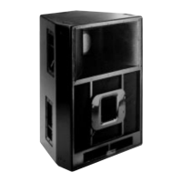
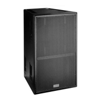
The trapezoidal enclosure shall be constructed of void-free cross-grain-
laminated birch plywood with integral bracing, and shall be tapered
so as to simplify construction of arrays. It shall be finished in black
catalyzed polyurethane. All external hardware shall be stainless steel or
shall be coated to protect against rust and corrosion. The front of the
system shall be covered with perforated steel grill, coated with vinyl to
dampen resonance and backed with open cell foam to protect against
dust. Hanging fixture attachment points shall be installed in the top
and bottom of the enclosure and mating clips shall be included. The
three-way full range loudspeaker system shall be the EAW model
KF650isR.
ARCHITECTS’ & ENGINEERS’ SPECIFICATIONS
ARCHITECTS’ & ENGINEERS’ SPECIFICATIONS
• Group C Hardware Technical Specifications
• Group C Price Lists
• APP Testing Procedures
• Weather Proofing Technical Specifications
• Structural/Mechanical Technical Specifications