1 Basic Tasks
· Connect audio signal cables, power cable, and, if needed, computer cable.
· Select the operating mode, input signal type(s), and temperature/humidity conditions.
· Select the signal source(s) for each input channel.
· Select the loudspeaker type for each input channel and assign the output channel(s).
· Adjust the amplifier and listening distance parameters for the output channel(s).
· Adjust input channel EQ, gain, polarity, and delay.
· For Generic Processing, use EAWPilot to adjust output channel EQ, gain, polarity, limiting, and delay.
2 Hardware Installation
2.1 AC MAINS
Universal power supply maximum operating range is 100 V to 240 V, 50 Hz to 60 Hz
Use supplied IEC-type ac mains cable with Nema connector for nominal 115 V or with Schuko connector for nominal 230 V.
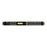
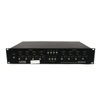
2.2 INPUTS A TO D
Cable: 2 conductor plus shield
Mating Connector: XLR-3 male
Analog:
Pin 1 Shield
Pin 2 Signal + or high
Pin 3 Signal - or low
Digital (AES/EBU):
Pin 1 Signal ground (shield)
Pin 2 Signal
Pin 3 Signal
2.3 OUTPUTS 1 TO 8
Cable: 2 conductor plus shield
Mating Connector: XLR-3 female
Analog:
Pin 1 Shield
Pin 2 Signal + or high
Pin 3 Signal - or low
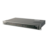
2.4 ETHERNET
For control of the processor using EAWPilot.
Cable: Ethernet CAT-5 cable or better
Mating Connector: RJ-45
Wiring Configuration: Crossover (supplied ) for direct to computer connection
Standard for connection to a hub or switch
2.5 U-NET
For networking audio and computer control between multiple U-Net enabled products.
Cable: Ethernet CAT-5 cable or better
Mating Connector: RJ-45
Wiring Configuration: Standard or crossover (supplied): the ports auto-sense the wiring
3 EAWPilot Software Installation
Install the EAWpilot™ program on a computer with the Microsoft® Windows operating system: XP, 2000, NT, ME, or Windows 98.
See EAWPilot’s Help file for EAWPilot’s operating instructions.