XRGI
®
- INSTALLATION GUIDE VERSION 1.0 2018
7
A B
C
1 4 52 6
3 7
8/9
10
12
14
13
15
16
18
17
11
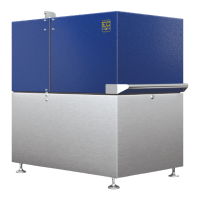
Fig. 2.05 - XRGI® 6/9
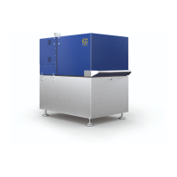
Fig. 2.06 - XRGI® 6/9
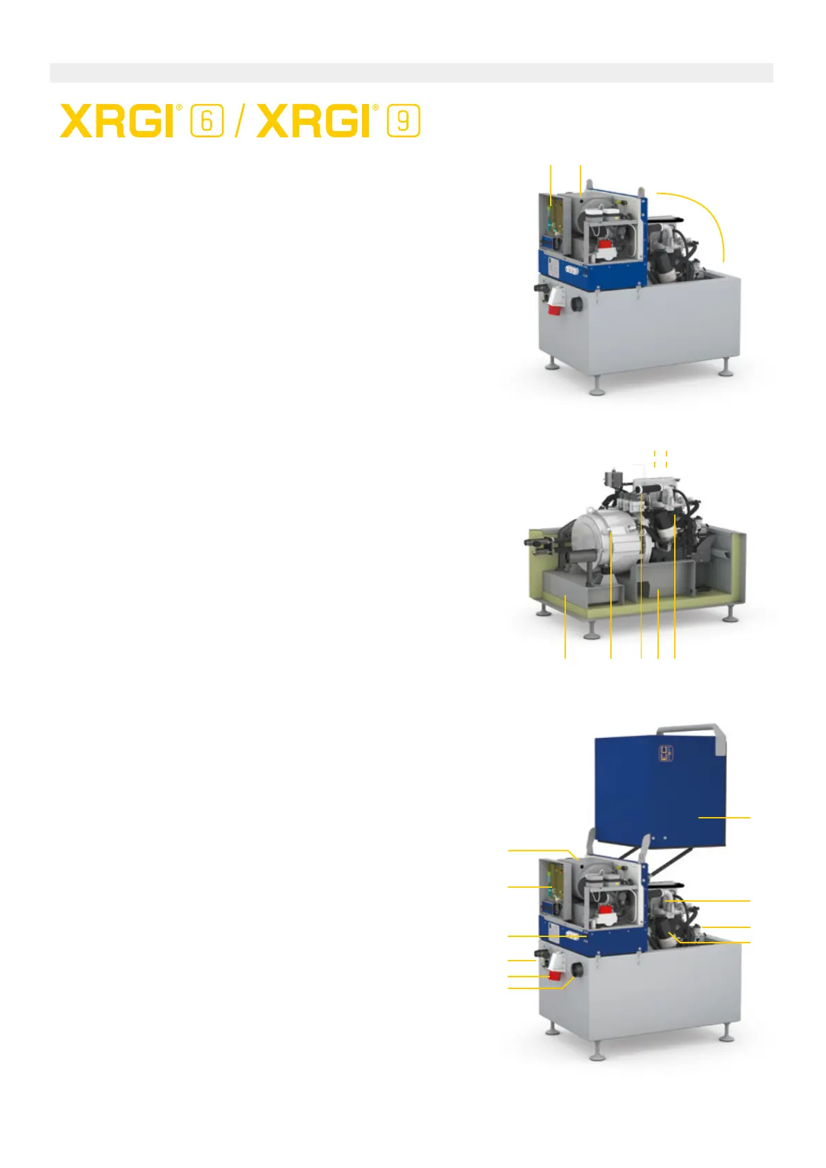
Fig. 2.07 - XRGI® 6/9
2.1.1 POWER UNIT
CONSTRUCTION
Legend:
A Electrical components and safety circuit
B Air filter and mixture control
C Sound- and heat-insulated engine compartment
1 Silencer (integrated)
2 Water-cooled generator
3 Exhaust gas cooler (not visible)
4 Oil sump
5 EC POWER gas engine
6 Oil separator
7 Catalyst (not visible (patented))
8 Primary circuit flow (1“ G)
9 Primary circuit return (1“ G)
10 Electrical connection
11 Exhaust gas connection (twin tube, di = 60 mm, da = 100 mm)
12 Gas connection (½“ G)
13 Air filter
14 Gas safety circuit
15 Cover with gas pressure springs
16 Spark plugs
17 Upright pipe for oil change
18 Oil filter (upright, water-cooled)
 Loading...