3 of 4
Before installation, examine the Directional LEDs for transit damage. Do not use damaged or broken parts.
The mounting location should be in accordance with the specications of the relevant state or territory school bus
regulations.
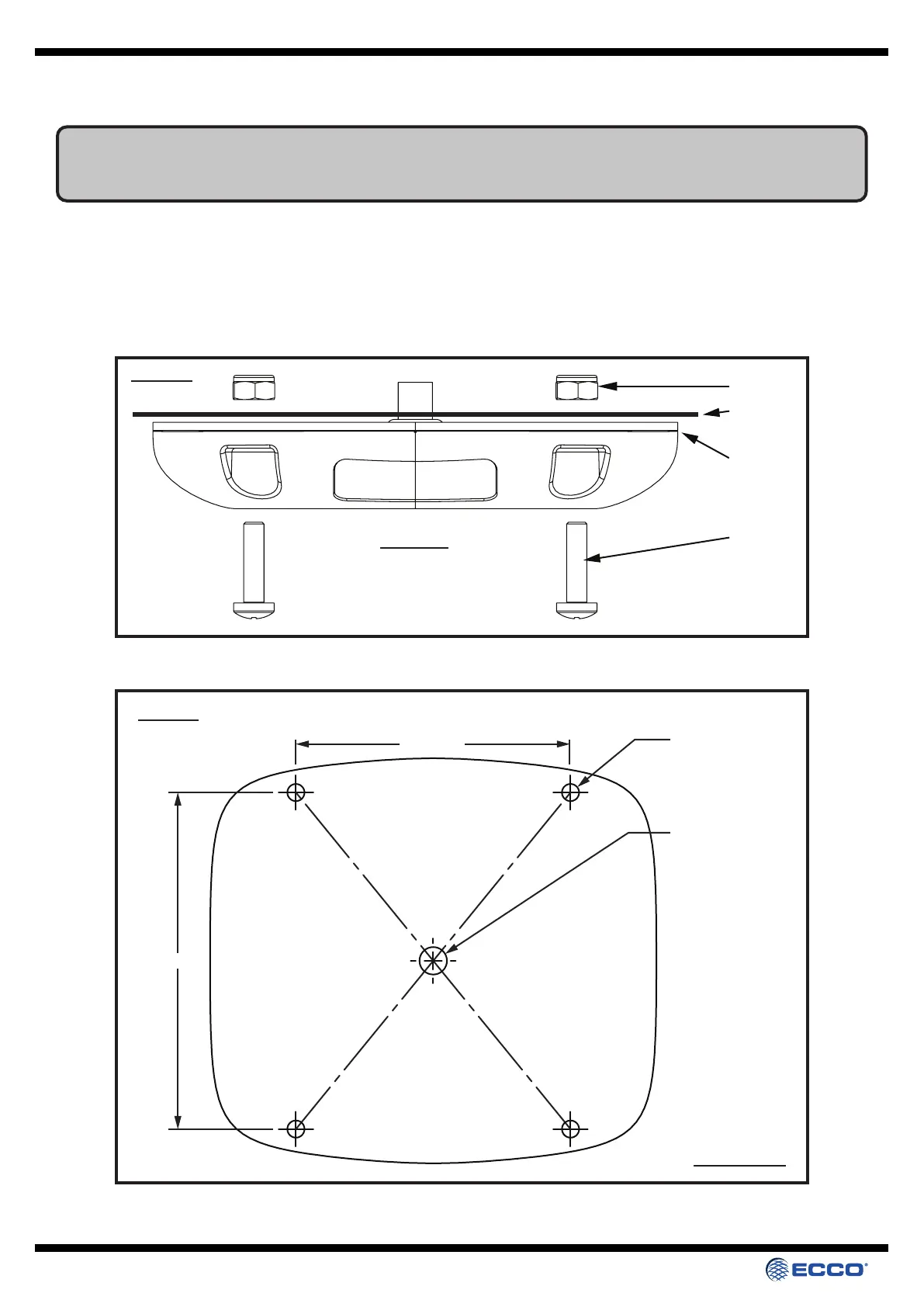
M5 Screw
M5 Nut
Gasket
Panel
Diagram 1.
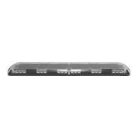
TOP VIEW
80.0 [3.14]
98.0 [3.85]
X4 Ø 5.0mm
MOUNTING HOLES
Ø 8.0mm
Diagram 2.
NOT TO SCALE
80mm
98mm
To mount the lamp, drill four M5 clearance holes in the required position in the vehicle, to match the four xing holes on the 200
Series LED School Bus Light. A further hole will be required to allow the cable to enter the vehicle (See diagrams 1 & 2 for
measurements). Fit the 200 Series LED School Bus Light using the four M5 screws and nuts as shown in the diagram below, with
the gasket provided between the 200 Series LED School Bus Light and the vehicle. Recommended tightening torque - 1.5Nm.
Mounting