EasyManua.ls Logo

Ecco 27 Series - User Manual

Ecco 27 Series
17 pages
Print Icon
To Next Page IconTo Next Page
Loading...
Page 1 of 18
IMPORTANT! Read all instructions before installing and using. Installer: This manual must be
delivered to the end user. This manual assumes installation by a suitably qualified Automotive Technician.
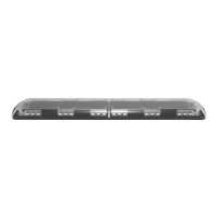
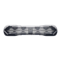
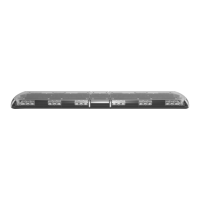
ECCO 27 Series Lightbars are versatile and powerful warning devices suitable for a range of vehicle types and duties. There are numerous
options and lengths available and the lightbars can either be mounted permanently to the vehicle or mounted using an optional roof
mounting kit. The 27 Series is suitable for many vehicle applications and features reflective LED modules, a durable aluminum chassis
and polycarbonate lenses. Available in seven standard configurations, the 27 Series can be configured with either centrally controlled or
independent flashing warning modules, offering a choice of either 3, 8, 12 or 22 LEDs per module, including dual color options. Stop-Tail-
Indicator, worklamp/takedown and alley light modules are also available as well as an integrated Safety Director to control the rear warning
modules independently.
Unpacking and Pre-Installation:
Carefully remove the lightbar and place it on a flat surface. Examine the unit for transit damage and locate all parts. If damage is found or
parts are missing, contact the transit company or ECCO. Do not use damaged or broken parts.
Ensure the lightbar voltage is compatible with the planned installation.
Installation and Operation Instructions
27 Series IF and CC Lightbars

Questions and Answers

Summary

Installation & Mounting

Permanent Mounting with Adjustable Mounting Feet

Details the process for permanently mounting the lightbar using adjustable feet on a vehicle roof.

Permanent Mounting without Adjustable Mounting Feet

Explains how to permanently mount the lightbar without using adjustable feet, using channels on the underside.

Vehicle Mounting Options

Pylon;Headache Rack Mounting

Instructions for mounting the lightbar onto a pylon or headache rack using mounting brackets and customer-supplied hardware.

Wiring Instructions

IF Series Wiring

Module Operation and CC Series Wiring

CC Series Wiring

Outlines wiring procedures for CC series lightbars, including power cable and control cable functions.

Emergency Mode Flash Pattern Selection

Flash Pattern Configuration - Unsynchronized

Emergency Mode Flash Pattern Selection - Synchronized

Arrowstik Flash Pattern Selection

TR Series Wiring

Emergency Mode Flash Pattern Selection (TR Series)

Troubleshooting

Overview

The ECCO 27 Series Lightbars are versatile and powerful warning devices designed for a wide range of vehicle types and duties, offering numerous options and lengths. These lightbars can be permanently mounted to a vehicle or installed using an optional roof mounting kit. They feature reflective LED modules, a durable aluminum chassis, and robust polycarbonate lenses, ensuring longevity and performance in various conditions.

Function Description:

The 27 Series Lightbars serve as emergency warning devices, providing high-visibility signals for emergency personnel and the public. They are available in seven standard configurations, allowing for customization to specific operational needs. Users can choose between centrally controlled or independent flashing warning modules, with options for 3, 8, 12, or 22 LEDs per module, including dual-color capabilities. Beyond warning functions, the lightbars can also integrate Stop-Tail-Indicator, worklamp/takedown, and alley light modules. An integrated Safety Director is available to independently control the rear warning modules, enhancing directional signaling capabilities.

Usage Features:

Mounting Options:

The lightbars offer several mounting methods to suit different vehicle types and user preferences:

  • Permanent Mounting with Adjustable Mounting Feet: This method allows for precise positioning on the vehicle roof. The adjustable feet slide along the lightbar base, enabling placement near curved roof edges. Once positioned, the feet are secured to the lightbar, and mounting holes are marked and drilled into the vehicle roof. Appropriate foot pads, designed for either flat or curved roof surfaces, are then attached, and the lightbar is secured with supplied hardware.
  • Permanent Mounting without Adjustable Mounting Feet: For a more streamlined installation, this method involves inserting carriage bolts into the lightbar channels. The lightbar is positioned over the vehicle center, and the mounting hardware is slid into place near the roof's curved edge. After marking and drilling mounting holes, the lightbar is secured to the vehicle.
  • Pylon/Headache Rack Mounting: This option is for vehicles equipped with a pylon or headache rack. Carriage bolts are inserted into the lightbar channels, and mounting brackets are loosely attached. The lightbar is then placed on the vehicle, and the brackets are slid into position. After securing the brackets to the lightbar with supplied washers and nuts, mounting hole locations are marked and drilled into the mounting surface. The brackets are then secured to the vehicle using customer-supplied hardware.
  • Strap Kit Mounting: Designed for specific vehicle models, this method uses mounting straps that hook into the vehicle's door frame gutter. The adjustable feet are loosely attached to the lightbar, and the lightbar is centered across the vehicle. The strap mount brackets are aligned with the door frame, and the feet are secured to the lightbar. Pan head screws are then tightened to secure the strap mount brackets to the lightbar feet and around the door gutters, ensuring the lightbar is centered and level.

Wiring and Control:

The lightbars come with detailed wiring instructions to ensure proper functionality and safety.

  • IF Series Wiring: IF series lightbars feature a dedicated ground wire and one or more positive power wires routed to the modules. The black ground wire must be connected directly to the battery. Amp ratings for each module type are provided in the specifications. A configuration-specific wiring key is included to identify the function of each wire. High-temperature wiring is recommended for connections passing through the engine compartment, and cable ties and grommets should be used to secure and protect all cables.
    • Flash Pattern Selection (IF Series): Individual light head flash patterns can be cycled by briefly shorting two short pads on the module with a wire or screwdriver. Holding the pads together for more than 5 seconds resets the light head to its default flash pattern. A thin layer of conformal coat may need to be scraped from the short pads for easier pattern changes.
  • CC Series Wiring: CC series lightbars utilize a 2-wire power cable and a 16-wire control cable. The entire power load is carried by the power cable, with the black ground wire connected directly to the battery. The 10 AWG red power wire requires a constant 10 to 16V power source with a customer-supplied in-line fuse, sized appropriately based on the total amp ratings of the modules (not exceeding 30A). The 16 control cable wires carry low-power input signals (30mA average) to control lightbar functions and are routed to a control switch or multiple switches. A configuration-specific wiring key is provided for wire functions, and high-temperature wiring, cable ties, and grommets are recommended for protection.
    • Master/Slave Corner Module Operation: The 360-degree corner modules consist of "master" and "slave" LED light engines. The "master" circuit board, located at the rear, powers the "slave" in the front position. Corner module pairs are connected by a sync wire, and the flash pattern is set by the master LED module.
    • Dimming Operation: 27 Series LED modules may include a low-power "Dimming" mode, which reduces light output. Users are cautioned to ensure adequate visibility when using this setting, as it may affect compliance with emergency warning light standards.
    • Emergency Mode Flash Pattern Selection (CC Series): Seven customizable emergency flash pattern modes are available, based on specific wire combinations. The default setting is unsynchronized, allowing each light head module group to be configured separately. To change a light head group flash pattern, power up the lightbar, apply power to the desired level mode wire, and then momentarily touch the BLK/RED Pattern select wire and the specific light head group wire to cycle through patterns. Holding these wires to power for more than four seconds restores the factory default flash rate.
    • Emergency Mode Flash Pattern Selection – Synchronized (CC Series): The seven emergency flash pattern modes can also be synchronized, condensing module groups to front and rear. To synchronize, power up the lightbar, apply power to the appropriate level mode wires and the BLK/RED Pattern select wire, then momentarily touch the RED wire to power. Once synchronized, the module group flash sequence defaults to OFF. To change a synchronized light head group flash sequence, power up the lightbar, apply power to the level mode wires and the BLK/RED Pattern select wire, then momentarily touch the appropriate light head group wire to power to cycle through sequences. To change a synchronized light head group flash pattern rate, follow a similar process, cycling through rates by momentarily touching the appropriate light head group wire to power. Holding the rate selection wire and BLK/RED wire to power for more than four seconds restores the factory default emergency warning flash rate.
  • Arrowstik Flash Pattern Selection (CC Series): The ArrowStik® functions (LEFT, CENTER-OUT, RIGHT, and FLASH) can be individually programmed for unique patterns and flash rates. The factory default for LEFT, CENTER-OUT, and RIGHT is "Building Fast," while FLASH defaults to "Drivers Side Cut - Front, corner & alley." To select a flash pattern, apply power to the lightbar and the desired function wire, then briefly touch the Pattern Select wire (RED/BLK) to power to cycle through patterns. Ensure no other function wire is powered during selection. Flash patterns marked with an asterisk can be selected in Fast, Medium, or Slow flash rates. Holding the BLK/RED and desired function wire to power for approximately four seconds restores the factory default ArrowStik flash patterns.
  • TR Series Wiring: TR series lightbars have a single cable with 11 colored wires, including a dedicated ground wire, a dedicated power wire, five control wires routed through the main driver board, and four additional wires supplying positive power directly to auxiliary modules like Work Lights, Alley Lights, Take Downs, or Stop/Turn/Tail (STT) modules. The 16 AWG black ground wire connects directly to the battery, and the 16 AWG red power wire requires a constant 10 to 16V positive power source with a customer-supplied 15A in-line fuse. The five control cable wires carry low current (30mA average) input signals and are routed to a control switch or multiple switches. A configuration-specific wiring key is provided, and high-temperature wiring, cable ties, and grommets are recommended.
    • Emergency Mode Flash Pattern Selection (TR Series): Seven customizable emergency flash pattern modes are available based on wire combinations. To change a flash pattern on a single emergency level mode, power up the lightbar, apply power to the desired level mode wire(s), then momentarily touch the GRN pattern select wire to positive power to cycle through patterns. Holding the GRN pattern select wire to positive power for approximately five seconds resets the flash pattern to the factory default.

Maintenance Features:

Lens Cleaning:

Occasional cleaning of the lenses is essential to ensure optimum light output. While the polycarbonate lenses are tough, they can scratch easily. Clean the lens and base with soap and water or a lens polish using a soft cloth. Avoid using solvents, as they may damage the polycarbonate material.

Lens Removal and Installation:

To remove a lens:

  1. Uninstall the four lens clips using a flat blade screwdriver.
  2. Insert the screwdriver into the gap along the lens edge and twist it to lift the lens. To reinstall:
  3. Ensure the lens gasket is not damaged or folded.
  4. Replace the clips by hooking them into the bottom lens slot and pressing the upper portion into the clip pocket.

LED Module Removal and/or Replacement:

To remove or replace an LED module:

  1. Remove the screw(s) securing the light head assembly to the lower lens.
  2. Lift the light head assembly and disconnect the wiring at the connectors. For re-assembly, reverse these steps, torquing the screw(s) to 10 in-lbs or 1.13 Nm.

Troubleshooting:

The manual provides a troubleshooting guide for common issues:

  • Does not function: Possible causes include poor power or ground connection or a blown fuse. For CC Lightbars, a green light on the central control board should flash when power is first applied and during flash pattern selection. Solutions involve checking wiring, replacing fuses, and ensuring proper connections.
  • Incorrect flash patterns: The possible cause is a wrong flash configuration. The solution is to cycle through flash patterns according to the supplied wire key and wiring instructions.

Important Note: Operating the vehicle without the outer lens installed on the product may result in damage that will not be covered under the warranty.

Ecco 27 Series Specifications

General IconGeneral
Light SourceLED
Frequency50/60Hz
MaterialAluminum
Model27 Series
Color Temperature3000K
FinishWhite

Related product manuals