Automatic Transfer Switch - VERSO 200 - Attachment 1
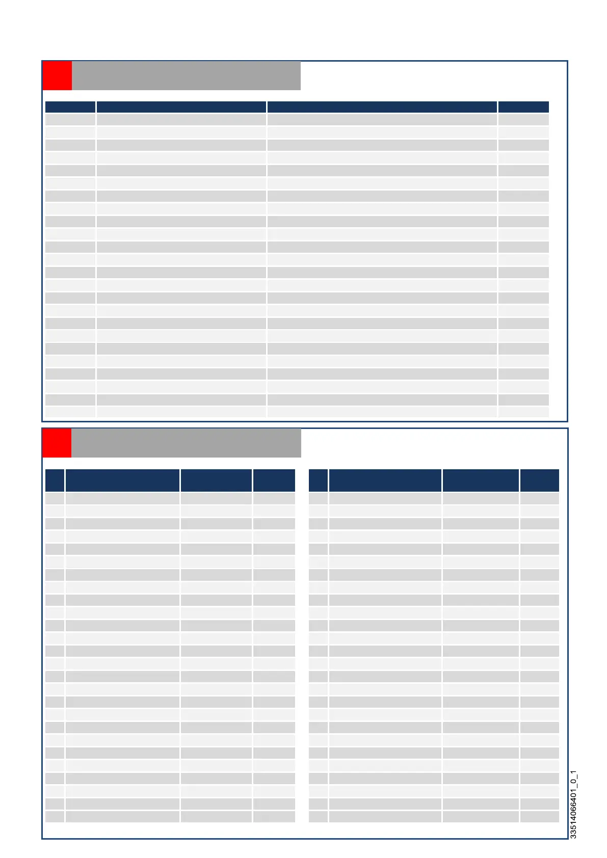
designation function Possible values Std settings
Mains
,
,
,
Unom Voltage in Volts 440, 415, 400, 380, 240, 230, 220, 208 AUTOCONF
(1)_U<% Default min mains U threshold Range of adjustment dependant on apparatus 15
Default min genset U threshold
Range of adjustment dependant on apparatus
(1)_U>% Default max mains U threshold Range of adjustment dependant on apparatus 10
Default max genset U threshold
Range of adjustment dependant on apparatus
(1)_Hz<% Default min mains F threshold Range of adjustment dependant on apparatus 5
Default min genset F threshold
Range of adjustment dependant on apparatus
(1)_Hz>% Default max mains F threshold Range of adjustment dependant on apparatus 5
Default max genset F threshold
Range of adjustment dependant on apparatus
ABC Direction of phase rotation ABC, ACB, OFF (no management) ABC
Adjustment of mains voltage measuring
Voltage gain adjustment (1=0,1V) (e.g.: )
(2)_V/V Adjustment of genset voltage measuring Voltage gain adjustment (1=0,1V) (e.g.:) 1000
Management of returns positions
YES=management, NO=no management
Bklight LCD screen backlight 99
Modbus Modbus card YES=with Modbus, NO=without Modbus NO
Default priority to EJP (*STOR)
(France only)
YES=application, NO=no application
(1)_OK? Manual confirmation of return to mains YES=confirmation required, NO=confirmation not required NO
No management of U and F limits
OFF=operation with limits, ON=operation without limits
Hyst/U% Hysteresis U value between 0% and 3% (of voltage limit) 2
between 0% and 2% (of frequency limit)
Measuring card adjustment
Adjustment of offset voltage of measuring card 5A07
List of parameters
A11
N° function Range of
adjustment
Standard
range
N° function Range of
adjustment
Std
settings
T01 Return source 2 0s to 999s 5 T27 Automatic configuration 0s to 999s
3
T03 max U source 1 0s to 999s 5 T29 Max critical U source 1 0s to 999s
1
T05 max U source 2 0s to 999s 5 T31 max critical U source 2 0s to 999s
5
T07 max F source 1 0s to 999s 5 T33 max critical F source 1 0s to 999s
1
T09 max F source 2 0s to 999s 5 T35 max critical F source 2 0s to 999s
5
T10
2
999
5
T36
0
/10
999
/10
5
default command source 2
s to
s
reserve
s to
s
T12 Source change over 0s/10 to 999s/10 10 T38 last fault source 2 0s/10 to 999s/10
5
U stabilisation source 1
s
to
s
reserve
s to
s
T14 U stabilisation source 2 0s/10 to 999s/10
30 T40 production demand 0s to 999s
10
T16
0
/10
999
/10
5
T42
0
999
15
Genset cooling source 1
s to
s
Default opening at source 1
s to
s
T18 Genset cooling source 2 0s to 999s
60 T44 Default opening at source 2 0s to 999s
5
test
s to
s
reserve
s to
s
T20 advance warning EJP (*STOR) 0min to 999min 20 T46 reserve 0s to 999s
3
T22 load shedding 0s to 999s
10 T48 reserve 0s to 999s
3
T24 return to home screen 0s to 999s
120
s=second min=minute s/10= tenth of a second U=voltage F=frequency *STOR= Short Term Operating Reserve
List of timers
A12
 Loading...