400 mm (15-3/4 in.)
220 mm
(8-5/8 in.)
ENGINE
END
F
L
i n s t a l l a t i o n
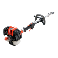
Tools Required: 8mm x 10mm Open End Wrench, Screwdriver,
4mm Hex Wrench.
1. Close choke and remove air lter cover.
2. Disconnect ignition stop leads (A) inner throttle linkage from
carburetor swivel (B), and remove throttle cable from bracket (C).
3. Remove power head from drive shaft.
4. Remove rear handle (G) from the drive shaft assembly.
5. Remove harness clamp (E) from drive shaft assembly.
6. Remove front handle (H).
7. Insert square nut (D) in lower handle bracket (I) and place bracket
on drive shaft 400mm (15 3/4 in.) from engine end of drive shaft.
8. Secure with lower handle bracket clamp (J) and three (3) 5x30
mm hex socket bolts.
9. Position harness clamp (F) 220 mm (8-5/8 in.) from engine end of
drive shaft assembly. Install 5x12 mm bolt, but DO NOT tighten at
this time.
10. Carefully attach drive shaft assembly to engine making sure inner
drive shaft engages into clutch socket.
11. Install upper U-Handle and bracket on lower bracket and secure
with one (1) 8 mm x 55 mm bolt (L) and large circular washer.
G
H
E
D
I
J
INSTALLATION INSTRUCTIONS U-HANDLE KIT
2