34
SRM-330ES/SRM-350ES
E
N
G
L
I
S
H
D
E
U
T
S
C
H
I
T
A
L
I
A
N
O
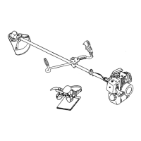
1. Loop handle
2. Screw M5× 35
3. Loop handle bracket
4. Nut
LOOP HANDLE
Assemble loop handle and bracket to drive shaft assembly.
Position handle in comfortable operating position and
tighten screws (M5× 35).
1. Linker Handgriff
2. Schraube M5× 35
3. Befetigungsplatte
4. Mutter
RUNDGRIFF VERSION (L-TYP)
Rundgriff und Halterung leicht an der Antriebswelle
befestigen.
Griff in einer bequemen Arbeitsstellung anbringen und die
Schrauben (M5× 35) festziehen.
IMPUGNATURA AD ANELLO
Montare l’impugnatura e la staffa senza stringere sull’albero
motore.
Regolare l’impugnatura in una posizione di lavoro
confortevole e serrare le viti (M5× 35).
1. Impugnatura anteriore
2. Vite M5× 35
3. Supporto
4. Dado
2
1
4
3
ASSEMBLING
(LOOP HANDLE VERSION)
ZUSAMMENBAU
(RUNDGRIFF-VERSION [L-TYP])
ASSEMBLAGGIO
(VERSIONE CON IMPUGNATURA AD ANELLO)
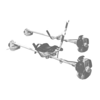
INSTALLATION OF BRACKET
Fit bracket to mounting portion of angle transmission and
fix the bracket by holding fitting plate pressed from beneath
and tightening 4 bolts (M5× 25) lightly.
Get notches and convexes of fitting plate to face
corresponding convexes and concaves of bracket, and fix
bracket tightening 4 bolts (M5× 25) securely.
1. Bracket
2. Bolt M5× 25
3. Convex of fitting plate
1. Supporto
2. Bullone M5× 25
3. Convesso della piastra
di raccordo
1. Runge
2. Schraube M5× 25
3. Fixierungspunkt in der
Befestigungsplatte
ZUSAMMENBAU DER RUNGE
Befestigen Sie die Runge am Winkelgetriebe indem Sie
die Befestigungsplatte von unten dagegen drücken und
die 4 Schrauben (M5× 25) leicht anziehen.
Bringen Sie die Kerbe und den Fixierpunkt der
Befestigungsplatte auf das entsprechende Gegenstück
der Runge und ziehen Sie die 4 Schrauben (M5× 25) fest.
MONTAGGIO DEL SUPPORTO
Adattate il supporto alla parte di montaggio della testina e
fissate il supporto tenendo la piastra di raccordo premuta
verso il basso e stringendo le 4 bulloni (M5× 25), ma non
troppo.
Fate combaciare gli incavi e i convessi della piastra di
raccordo in modo che convessi e concavi del supporto
corrispondano e fissate il supporto stringendo bene le 4
bulloni (M5× 25).
4. Fitting plate
5. Notch of fitting plate
4. Befestigungsplatte
5. Kerbe in der
Befestigungsplatte
4. Piastra di raccordo
5. Incavo della piastra di
raccordo
1
2
3
4
5