Fitting Instructions - (continued)
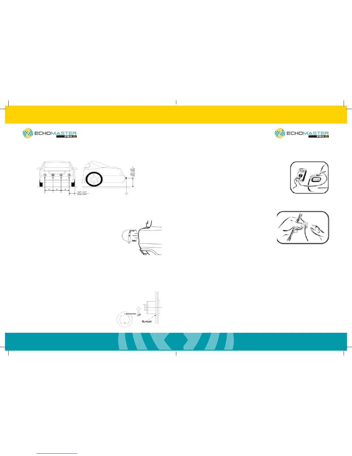
Sensor Install: Sensors must be installed in order 1-4 from left to right with control
module harness entering trunk near sensor #4. If only using 2 sensors for the install, it
is recommended to use sensors 2 and 3.
Choosing the Correct Angle Sleeve (Optional angle gauge: SP1022)
Vehicle is parked on at and level ground and
the parking brake is set. Place the Angle Gauge
at against the surface of the bumper. The
swingarm will point to the correct measurement.
DO NOT CONTINUE TO NEXT STEP IF ARM
FALLS BEYOND THE LAST LINE ON THE MARKER!
This means that the placement is too steep; re-evaluate
placement and nd a better area.
Drilling Holes and Installing Sensors
Warnings / Precautions: Please consult with us before installing on a vehicle with any
rear or front mounted external appliances, like spare tires, bike racks, brush guards,
etc, which may interfere with the system’s detection and cause false detection.
Using the provided Hole Saw, cut the
sensor holes. Always wear approved
safety glasses when drilling and use
caution. If drilling a metal bumper, coat
edges of holes with Zinc Galvanizer, a
rust inhibitor.
Ensure correct angle sleeve
is being used. Insert sensor
with the “up” marking
facing up.
(2) Mount Sensor(1) The Sensor Holes
Fitting Instructions - (continued)
Connecting the Power Harness
NOTE: It is recommended to solder all connections.
To nd reverse power, remove tail light and
examine where and what wires plug into the reverse
bulb. Locate and verify with a volt meter. The wire
carries 12 volts when in reverse and 0 volts when out
of reverse.
Once the reverse wires are found,
connect the red wire from the power
harness to it. Connect the black ground wire
from the unit’s wiring harness to the vehicle’s
ground wire. Route cable to
control module and plug in.
NEVER USE A TEST LIGHT TO PROBE WIRES
Running Sensors to Control Module
Many vehicles will have factory grommets to allow routing of wires from the outside
to the inside of the vehicle. If you are drilling a hole through a metal body panel
to route your sensor wires into the passenger compartment, determine where the
sensor wires will enter into the passenger compartment and route to control module.
Control module must be on right (passenger side) of vehicle.
Mounting Speaker
The speaker has 3 adjustment positions: Hi, Low, and Off. You usually want to keep
the speaker on the same side of the vehicle as the control module for ease. Clean the
mounting area with the supplied alcohol pad, afx adhesive to the back of the speak-
er, and rmly press the speaker into place. Route speaker cable to control module and
plug into power harness.
If using display, please refer to PA-DISPLAY user manual for mounting instructions.
PS-RBP/PS-RDIS
ParkAlert Rear Sensor System
with Buzzer or Display
PS-RBP/PS-RDIS
ParkAlert Rear Sensor System
with Buzzer or Display
 Loading...