24
FLS Platinum Instruction Manual
FLS Platinum Installation
Instructions
Some Common Faults
Display or transmitter box doesn’t switch on (no display or LEDs lit):-
• Battery not connected
• Battery voltage too low
Transmitter box LED not flashing:-
• No power to display unit or display not switched on
• 12m data cable not connected properly
• Power not cleanly applied to transmitter box - re-make connection
No seabed visible and transmitter box LED is flashing:-
• Transducer not connected (or not connected properly) - use Test Mode
• Incorrect range selected (try using the ‘Auto’ setting!)
Poor seabed picture or excessive noise:-
• Suitable range not selected (try to fill screen with seabed)
• Poor connection of transducer
• Battery voltage low - use Test Mode to check Tx voltage
• Transducer mounted at an angle
• Turbulence at transducer location
• Interference from other 200KHz sounders (same boat or other boats)
• Turbulence/wake from other boats
• Polluted water or Plankton bloom (usually early summer)
• Dirty transducer/covered with barnacles
• Choppy sea state - can cause surface noise
FLS Platinum - Fault Finding
9
FLS Platinum Instruction Manual
Test Mode
This mode allows the user to obtain diagnostic data about the unit should a fault
occur with the display, transmitter box or transducer. The page key scrolls between 3
test pages.
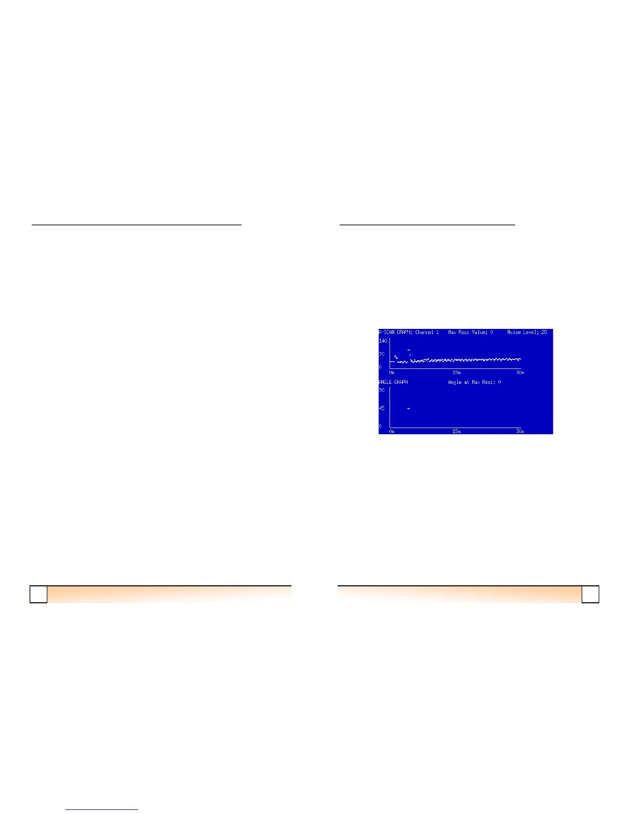
A-Scan and Angle Graphs
These graphs display the sonar signal strength and associated calculated angles over a
30m range. If the depth is greater than 30m, these graphs will not show the received
seabed echo and angle of the seabed.
FLS Platinum Operating
The A-Scan and Angle Graphs
The A-scan graph of a flat seabed will show a low signal level up to the depth of the
seabed and should then increase significantly to a higher lever when the sebed is
reached. This is the returned echo from the seabed. The angle graph will show angles
between 0 and 90 degrees. The angles should start at about 60-70 degrees at the
seabed depth and will decrease gradually as the range of the received echo increases
(for a flat seabed).
The up arrow key allows the user to scroll between the 3 receive channels (A-Scan
graph only). Each channel must be displaying similar A-Scan graphs for the angle to
be calculated correctly. Low or very different echo levels on any of the 3 channels
will cause poor performance of the FLS unit.
 Loading...