ECI 1000-U LCD Installation Manual
Electronic Controls, Inc.
7073 North Atlantic Ave. Cape Canaveral, FL 32920
800-633-9788
www.eciamerica.com P a g e | 8
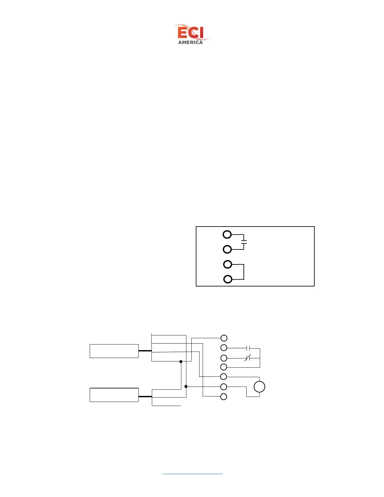
6.2.3 X13 Controller interface
The voltage of controller interface signals are adjustable through the Input Voltage parameter located
under the Edit Parameters menu. These signals are AC/DC compatible.
DO3 – Open limit output to controller
DO10 – Open command input
DO7 – Close command input
DO4 – Nudging command input
DO18 – Door locking command input
DO17 – Close limit output to controller
6.2.4 X9 Connections
0V – Negative or return voltage for 54P from operator
54P - +54VDC power source from operator
RB1 and RB2 - External braking resistor located in operator
A1 and A2 – 48VDC output to motor
6.2.5 X4 and X5 connections
CAM switch assembly connectors. Refer to Figure 5 – CAM Switch Wiring
6.2.6 X7 and X10 Connectors
Heavy Door option connectors. These 2 connectors are the same pinout located on opposite sides of the
board for installation convenience.
24P – +24VDC power output
HDP – Heavy door +24VDC input
HDN – Heavy door 24VDC common input
0V – 24VDC common output
6.2.7 X8 Infra-red Door Detector Connections
Compatible with Memco model 640. Dry relay contacts to controller 250VAC/3A, 24VDC/3A