960E Installation Manual
ECI Telecom Ltd. Proprietary 36
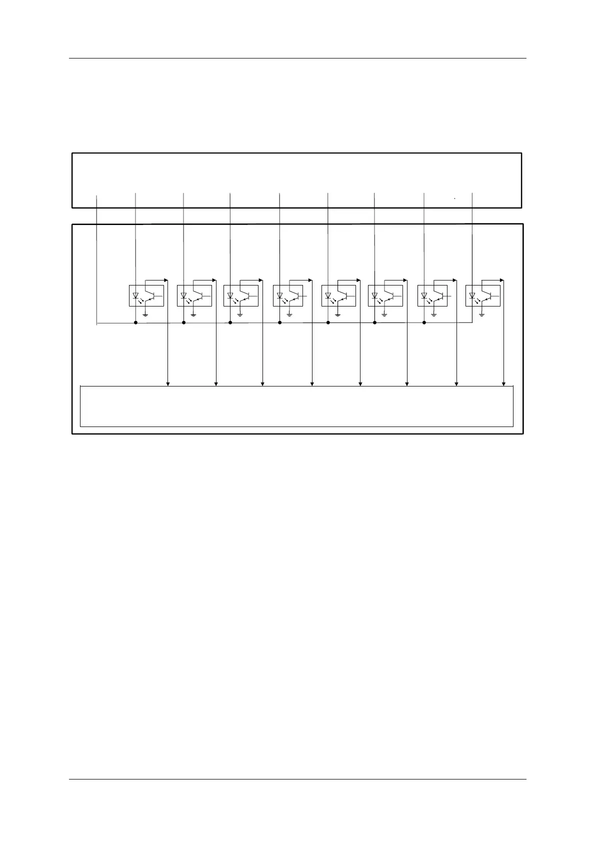
B.1.3. IN-ALARM
The following figure shows the IN_ALARM circuit connection. P48V
DC
nominally is
required for each in alarm and -48/60V
DC
for common.
CPA
IPNI
CCP
ALM_COMM
IN_ALR1
IN_ALR2 IN_ALR3
IN_ALR4
IN_ALR5
IN_ALR6
IN_ALR7 IN_ALR8
-48/60VDC
P48VDC P48VDC
P48VDC P48VDC P48VDC P48VDC
P48VDC P48VDC
Alarm_Connection_circuitry.vsd
Figure 23. In-Alarm Connection Circuitry
 Loading...