(CONTINUED)
You have now removed your Geo Grip Frame from the
Geo Body and have access to the Solenoid Assembly
and Break Beam Sensor System if maintenance on
either is required (SEE FIGURE 12.6).
To install the Frame, carefully thread the Solenoid
and the Break Beam Sensor System wiring harnesses
through the access hole in the top of the Frame and
line the frame up so that the Rear Frame Screw sits in
the access hole (SEE FIGURE 12.7).
Be careful not to trap or pinch the BBSS or Solenoid wires
behind the rear frame screw or between the body and
frame.
Slide the frame forward so that it sits completely flush
with the Geo Body and using the short arm of a 1/8”
hex key, tighten the Rear Frame Screw into place (SEE
FIGURE 12.8).
Insert the Front Frame Screw into its designated
position at the front of the Frame and using a 1/8” hex
key tighten it into place (SEE FIGURE 12.9).
HOW TO REMOVE THE
FRAME
Disconnect any hosing and unscrew the Inline
Regulator from the Front Regulator Mount (FRM) as
detailed in the “Cleaning the Inline Regulator” section
of this Maintenance Guide.
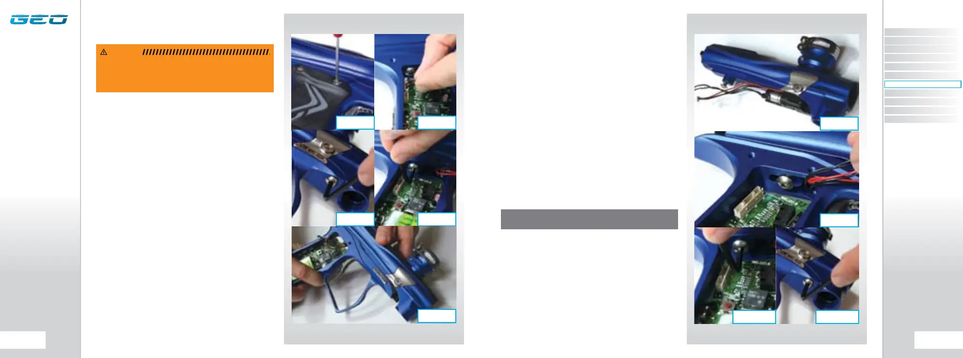
Using a 5/64” hex key, remove the six screws that attach
the Geo Rubber Grips to the Geo Grip Frame (SEE
FIGURE 12.1).
Unplug the Solenoid and the Break Beam Sensor
System wiring harnesses from their respective ports on
the Geo Circuit Board (SEE FIGURE 12.2).
Using a 1/8” hex key, undo and remove the Front Frame
Screw (SEE FIGURE 12.3). Using the short arm of a 1/8”
hex key, loosen the Rear Frame Screw a full turn (SEE
FIGURE 12.4). Slide the Frame backwards approximately
half an inch so that the Rear Frame Screw disengages
from the Frame and remove the Frame from the Geo
Body taking care not to damage any wires (SEE FIGURE
12.5).
WARNING: DE-GAS YOUR MARKER, DISCHARGING ANY
STORED GAS IN A SAFE DIRECTION, AND REMOVE THE
BARREL, LOADER AND AIR SYSTEM TO MAKE THE MARKER
EASIER TO WORK ON.
FIG 12.7
FIG 12.6
FIG 12.9
NOTE: CHECK THAT NO WIRES ARE TRAPPED BEFORE
TIGHTENING DOWN THE TWO FRAME SCREWS.
FIG 12.8
FIG 12.4
FIG 12.2FIG 12.1
FIG 12.5
FIG 12.3
CONTENTS
ORIENTATION
QUICK SET-UP
USING YOUR GEO
ADVANCED SET-UP
MENU TREE
MAINTENANCE
FAULT FINDING
SERVICE CENTERS
PARTS LIST
SPARES & ACCESSORIES