(CONTINUED)
Clean off any dirt, debris, paint or grease from the Spool
Pack and inspect the o-rings for any signs of wear or
damage (SEE FIGURE 13.14). If any of the o-rings on
the Spool Pack are damaged replace the entire Spool
Pack. Using a dry Q-tip clean the inside of the minifold
where the Spool Pack resides ensuring that any dirt,
debris and old grease is removed (SEE FIGURE 13.15).
Lubricate every o-ring on the outside of the Spool Pack
thoroughly with Eclipse Grease and insert the Spool
Pack into the minifold making sure that the screw hole
in the end lines up with the hole in the minifold
(SEE FIGURE 13.16).
Using an appropriate sized Phillips head screwdriver,
replace and tighten the Spool Pack Retaining screw
into the minifold (SEE FIGURE 13.17).
Hold the Solenoid Assembly onto the bottom of the
Geo body, taking care to line it up correctly with the
screw holes in the body and to avoid pinching the BBSS
wires underneath it (SEE FIGURE 13.18). Use a 5/64” hex
key to tighten the two screws that hold the Solenoid
Assembly onto the Geo body (SEE FIGURE 13.19).
You have now successfully stripped and cleaned your
Geo Solenoid Assembly.
NOTE: DO NOT OVER TIGHTEN THE SCREWS IN THE
SOLENOID ASSEMBLY.
(CONTINUED)
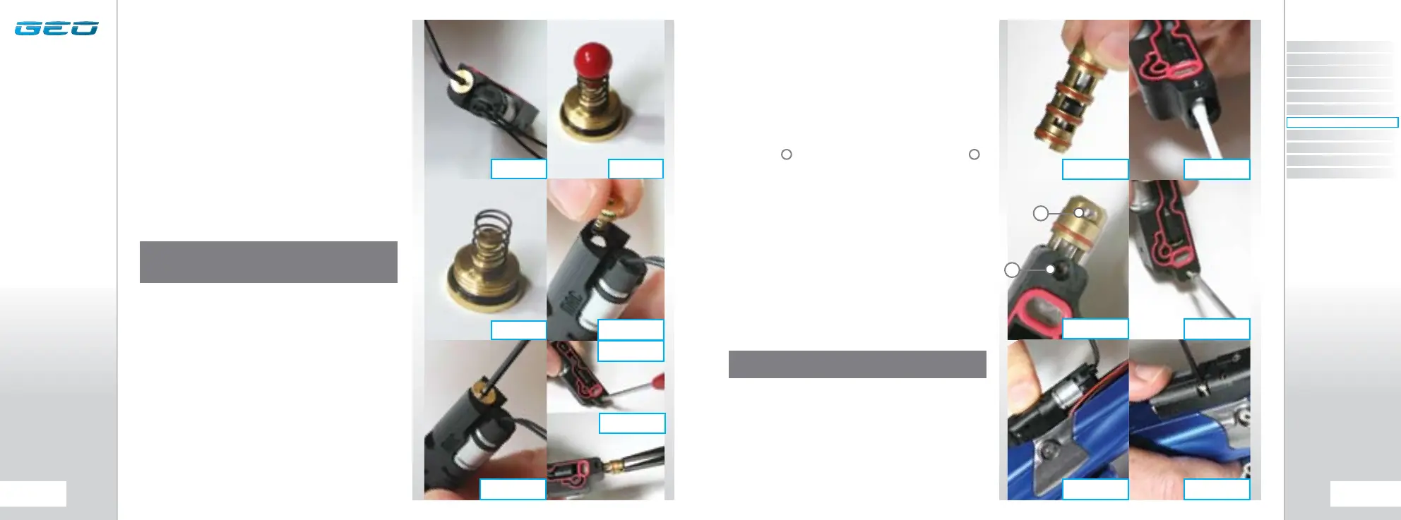
Using a 5/64” hex key, unscrew and remove the Back-
check Assembly from the minifold (SEE FIGURE 13.7).
The Back-check Assembly comprises of three parts; the
Back-check Ball, the Back-check Spring and the Back-
check Cap (SEE FIGURE 13.8). If the Back-check Ball or
Spring is deformed or damaged replace as necessary
using authentic Geo Spares.
Rebuild the Back-check Assembly by placing the Back-
check Ball into hole in the minifold and then attach
the Back-check Spring to the end of the Back-check
Cap as shown in FIGURE 13.9. Holding the minifold on
its end, insert the connected Spring and Cap into their
designated hole in the minifold (SEE FIGURE 13.10).
Using a 5/64 hex key screw the Back-check Cap back
into the minifold to hold the contents of the Back-
check Assembly in place (SEE FIGURE 13.11).
Using an appropriately sized Phillips head screwdriver,
remove the Spool Pack Retaining screw from the
minifold (SEE FIGURE 13.12) and using a pair of needle
nosed pliers remove the Spool Pack from the minifold
(SEE FIGURE 13.13).
NOTE: IF ANY OF THE COMPONENTS OF THE BACK-
CHECK ASSEMBLY ARE DAMAGED OR NOT FUNCTIONING
CORRECTLY IT WILL CAUSE THE MARKER NOT TO FIRE.
A
B
A
FIG 13.14 FIG 13.15
FIG 13.16
FIG 13.17
FIG 13.18 FIG 13.19
FIG 13.12
FIG 13.13
FIG 13.7 FIG 13.8
FIG 13.9
FIG 13.11
FIG 13.10
B
CONTENTS
ORIENTATION
QUICK SET-UP
USING YOUR GEO
ADVANCED SET-UP
MENU TREE
MAINTENANCE
FAULT FINDING
SERVICE CENTERS
PARTS LIST
SPARES & ACCESSORIES
 Loading...