Part 5.1 Further Venting Options: PVC/CPVC/Polypro single pipe
REQUIREMENTS FOR INSTALLATION OF SINGLE PIPE VENTING ON ECO-KING BOILERS IN CANADA
Venting PART 1 Installations must be made with ANY vent pipe system certified to ULC-S636. Examples are, M&G
Duravent, Cox Geelen and Centrotherm polypropylene. They are approved vent manufacturers in Canada supplying
vent material listed to ULC-S636, but are not exclusive. Any PP manufacturer approved to ULC S-636 can be used.
Please see Table 1 below for an outline.
Table 1 Approved exhaust vent material on Eco-King Boilers
Standards for installation in:
**When transitioning to 2” venting, a 3” to 2” reducing adapter should be used**
NOTE: See Part 3 for PP vent instructions
NOTE: Eco-King Boilers have a high temp flue gas protection switch
Venting PART 2 Air intake must be brought into the boiler from outside, with one exception outlined in part 4 of this
addendum, see page 4. Approved materials for air intake are listed in Table 2 below:
Table 2 Approved air intake material for Eco-King Boilers
Standards for installation in:
Venting PART 3 The use of single pipe Eco-King (M&G) polypropylene or any polypropylene venting rated to ULC
S-636 is now available to be used with Eco-King Boilers. No special adapter needed. Please review the following
instructions:
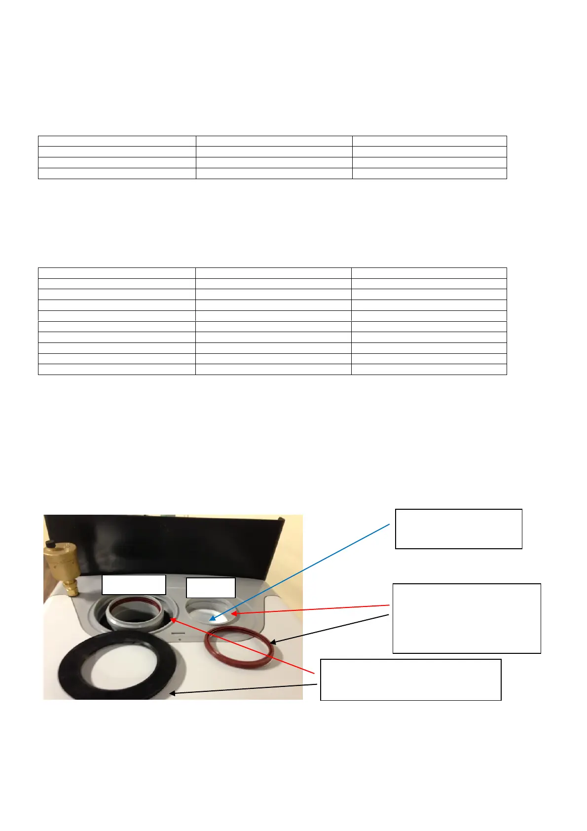
It is possible though to use a two pipe system (one for intake and one for exhaust) by following these steps:
1) A black O-ring seal (see figure 1) on the concentric air intake portion must be used to block air intake (see
figure 3). This black O ring is supplied with boiler. It is placed with the installation manuals in a plastic bag
2) Then the white cap on the separate single pipe air intake must be removed from the boiler (see figure 1)
3) Add the supplied O-Ring seal, which comes in a plastic bag with the install manuals (see figure 2)
4) Now the boiler is ready to be used in a two pipe system. Just connect any two 3” (80mm) polypropylene
fittings to the exhaust and intake. Look at Figure 4 to see how the two pipes system will look
32
O-Ring seal to cover air intake on
concentric opening. Insert where red
arrow points (see figure 3)
O ring seal for air intake when
using two pipes. To be placed
where red arrow points (see
figure 2)
Remove white cap to open
air intake inlet
 Loading...