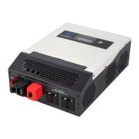
This document describes the ECO-WORTHY 3000W 24V Pure Sine Wave Off-Grid Inverter, a high-frequency sine wave inverter designed for various off-grid systems such as vehicle systems, security monitoring systems, emergency lighting systems, household power systems, field power systems, and other systems requiring higher power quality.
Function Description
The inverter adopts a fully digital intelligent design and voltage-current dual closed-loop control algorithm, offering fast response, high conversion efficiency, low Total Harmonic Distortion (THD), and high reliability. It provides pure sine wave output and input to output electrical isolation. Key features include input protection (low-voltage, over-voltage), output protection (overload, short circuit, overheating), and an RS485 communication port for remote monitoring. An external switch design is matched with EPEVER products to expand inverter control functions and reduce power consumption. The inverter also features diversified AC output sockets and is certified to EN/IEC62109-1/2, EN61000-6-2/4, and FCC approved. For inverters with 12V/24V input voltage, the RS485/RJ11 port has NO communication isolation design, while for inverters with 48V input voltage, it has communication isolation design.
Important Technical Specifications
The manual details two models: IPT3000-21 and IPT3000-22.
- Continuous output power: 3000W at 35°C @Rated input voltage.
- Surge power: 6000W@5S.
- Surge current when power on: < 100A.
- Output voltage:
- IPT3000-21: 100VAC/110VAC (±3%); 120VAC (-7%~+3%).
- IPT3000-22: 220VAC (±3%); 230VAC (-6%~+3%); 240VAC (-9%~+3%).
- Output frequency: 50/60Hz ± 0.2%.
- Output wave: Pure Sine Wave.
- Output distortion THD: THD ≤ 5% (Resistive load).
- Load power factor: 0.2 ~ 1 (Load power ≤ Continuous output power).
- Rated input voltage: 24VDC.
- Input voltage range: 21.6 ~ 32.0VDC.
- Rated output efficiency:
- IPT3000-21: > 87.0%.
- IPT3000-22: > 90.0%.
- Max. output efficiency (30% loads):
- IPT3000-21: > 91.5%.
- IPT3000-22: > 94.0%.
- Idle current: < 0.15A.
- No-load current: < 1A.
- RS485 com. port: 5VDC/200mA.
- Input terminal: M6.
- Dimension (L x W x H): 521 × 270 × 143mm.
- Mounting size: 495 × 145mm.
- Mounting hole size: Φ6mm.
- Net Weight:
- IPT3000-21: 8.8kg.
- IPT3000-22: 8.5kg.
- Working temperature: -20°C ~ +60°C (Refer to the Derating Curve).
- Storage temperature: -35°C ~ +70°C.
- Relative humidity: ≤ 95% (N.C.).
- Enclosure: IP20.
- Altitude: < 5000m (If the altitude exceeds 1000 meters, the rated power will be reduced according to IEC62040.).
- Certifications: EN/IEC62109-1, UL458 (Products with 12/24V input voltage support), CSA C22.2#107.1, EN61000-6-2/EN61000-6-4, FCC 47 CFR Part 15, Subpart A, IEC62321-3-1.
Usage Features
The inverter supports various settings and protections.
- Power Saving Mode (PSE/PSO): Users can enable a power saving mode and set the PSI/PSO value via a remote meter. The minimum power step is 1VA. The inverter automatically exits power saving mode and resumes work when the actual load power exceeds the PSO.
- Other Parameters: Users can set the baud rate, output voltage class, and output frequency class via the remote meter.
- Input Voltage Protection: Includes over voltage limiting, over voltage reconnect, low voltage reconnect, and low voltage disconnect protections. Detailed status is shown on the LCD display.
- Overload Protection: The inverter automatically shuts down and cannot be recovered automatically when an overload occurs. After cutting down some of the loads, users need to restart the inverter to recover the AC output.
- Output Short Circuit Protection: The inverter recovers automatically three times (recover after 5s, 10s, and 15s separately). After three times recovery attempts fail, users need to restart the inverter to recover the AC output.
- Inverter over Temperature Protection: The inverter stops working when the temperature of the heat sink or internal modules is higher than a set value and resumes work when the temperature is lower than a set value.
- GFCI Socket Testing: For models with GFCI sockets, it is recommended to test them after power-on to ensure proper operation. This involves connecting a circuit breaker and an AC load, then observing the status of the GFCI socket.
- Connection Diagram: The manual provides a clear connection diagram for connecting the inverter to a battery and domestic appliances. It is recommended to directly connect the inverter DC input terminal to the battery.
- Battery Connection: A fuse must be installed on the battery side. Fuse voltage is 1.5 to 2 times the inverter's rated voltage, and fuse current is 2 to 2.5 times the inverter's rated current. The distance between the fuse and the battery cannot be farther than 150mm. The AC loads should be determined by the continuous output power of the inverter. The surge power of the AC load must be lower than the instantaneous surge power of the inverter, or the inverter will be damaged. The N pole of the AC output port cannot be grounded.
- Wiring: The wire size for the ground connection must be thicker than or equal to the AC output wires. Ensure correct polarity for poles' leads.
- Installation: Read all installation instructions carefully. Wear eye protection and rinse with clean water for battery acid contact. Keep the battery away from any metal objects. Avoid loose power connectors, corroded wires, and high heat. The DC input voltage must strictly follow the parameter table. Select system cables according to 3.5A/mm2 or less current density. Avoid direct sunlight and rain. Do not open or touch internal components immediately after turning off the power switch. Do not install the inverter in a harsh environment. Do not touch the wiring connection to avoid electric shock. Do not touch the fan while it is working. The inverter should be installed in a place with sufficient airflow, and a minimum clearance of 150mm from the upper and lower edges is recommended to ensure natural thermal convection. It is not recommended to install the product in an enclosed cabinet where device cooling will be influenced.
Maintenance Features
Regular maintenance is recommended at least two times per year for good performance.
- Make sure no block on airflow around the inverter. Clean up any dirt and fragments on the heat sink.
- Check all the naked wires to ensure insulation is not damaged by sun exposure, frictional wear, dryness, insects or rats, etc.
- Verify the indicator display is consistent with the actual operation.
- Confirm that terminals have no corrosion, insulation damage, high temperature, burnt/discolored sign, and tighten terminal screws to the suggested torque.
- Clear up dirt, nesting insects, and corrosion in time.
- Check and confirm that the lightning arrester is in good condition. Replace a new one in time to avoid damaging the inverter and other equipment.
- The inverter is allowed to restart after removing the faults, which affects the safety performance.
- There are no serviceable parts inside. If any maintenance service is required, please contact the local distributor or service personnel.
- It is recommended to check the inverter with testing equipment to ensure no voltage and current.
- When conducting electrical connection and maintenance, post a temporary warning sign or put up barriers to prevent unrelated personnel from entering the electrical connection or maintenance area.
- An improper operation of the inverter may cause personal injury or equipment damage.
- It is recommended to wear an antistatic wrist strap or avoid unnecessary contact with the circuit board.