Premier Tech Aqua 26/32 Polyethylene Ecoflo
®
Coco Filter– Installation Guide CAN/USA
339975 Rev. 5.0
6.8 Final backfill of the biofilter or PACK unit
Before completing the final backfill, do not forget to pass
the two electrical wires from the house and pass through
the tank wall by the watertight connector (installation of
those may be required of some models) (cf. following
section).
For the PACK model fill carefully by hand under the pipe
which connects the septic tank and the Ecoflo
®
unit to
assure that there is no air gaps between the pipe and the
backfill. Premier Tech Aqua recommends wetting backfill
sand to improve compaction. Do not compact soil above
the PVC pipe after the final backfill.
Complete the backfill. Note that the backfill material must be laid down rather than pushed onto the reactor. For
that reason, do not use a bulldozer at this stage. The backfill material must be sandy and free of rocks or stones.
Plan for the layer of vegetation and make sure that the system’s covers are 2" (50 mm) above the surface once the
landscaping has been completed.
Make sure that the profile of final grade is such that runoff water flows away from the septic system.
6.9 Verification and electrical connections of the pump (models equipped with a built-in pump)
Step 1 – Verification of the pump
Make sure not to send debris (earth, clean stone, plastic tie-raps, electrical connectors, tape,
etc.) in the shell while making the electrical connections. All debris must be removed. Carry out
a visual inspection of the access well’s interior components (float shaft, floats, pump) to make
sure that everything is in the right place.
Step 2 – Electrical connections
A professional electrician must make the electrical connections. To make the system’s electrical
connections (from the residence to the system), two (2) double-stranded electrical wires are
needed and it is recommended to use a pipe to protect the wires that are to be buried. The choice
of the appropriate wire size must also be made by a professional electrician. One of these wires
will provide the power supply, whereas the other one will send current from the alarm float to the
alarm box (Item A) or the control panel (when required).
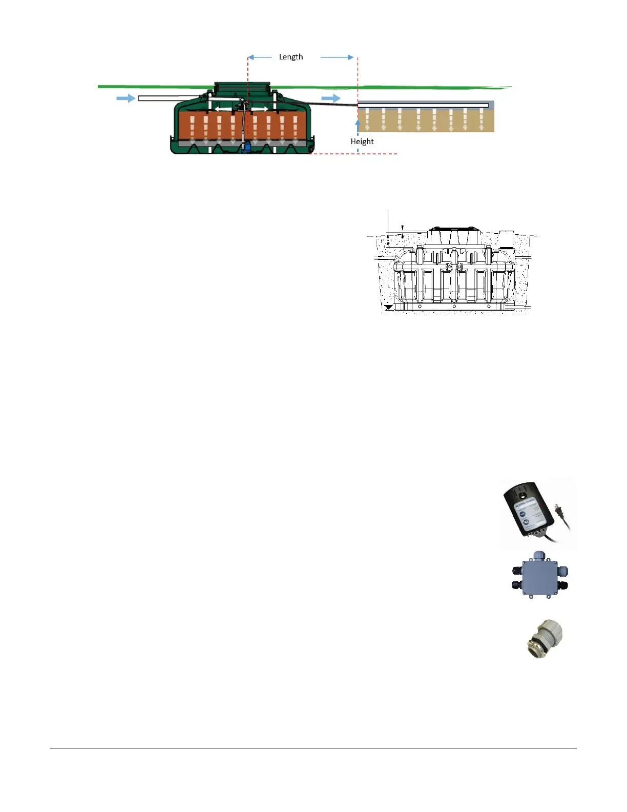
The use of watertight electrical connectors (Item C) is required to pass through the interior of the
secondary or main access according to the model. The wires must enter beneath the channel
built into the access. Use a reference point to this effect (cf. secondary access diagram when
applicable).
Make the appropriate electrical connections using the parts provided (electrical junction box [Item B], watertight
wire screw connectors and electrical connectors [Item C]). First, the float and pump wires’ plugs must be removed
by cutting them at 5 cm (2") from their ends. The junction box is located on the insulating panel of the secondary
or main access depending on the model. In the case of models 5.7 and 7.3 only, drill two (2) holes measuring 2 cm
 Loading...