Premier Tech Aqua 27/32 Polyethylene Ecoflo
®
Coco Filter– Installation Guide CAN/USA
339975 Rev. 5.0
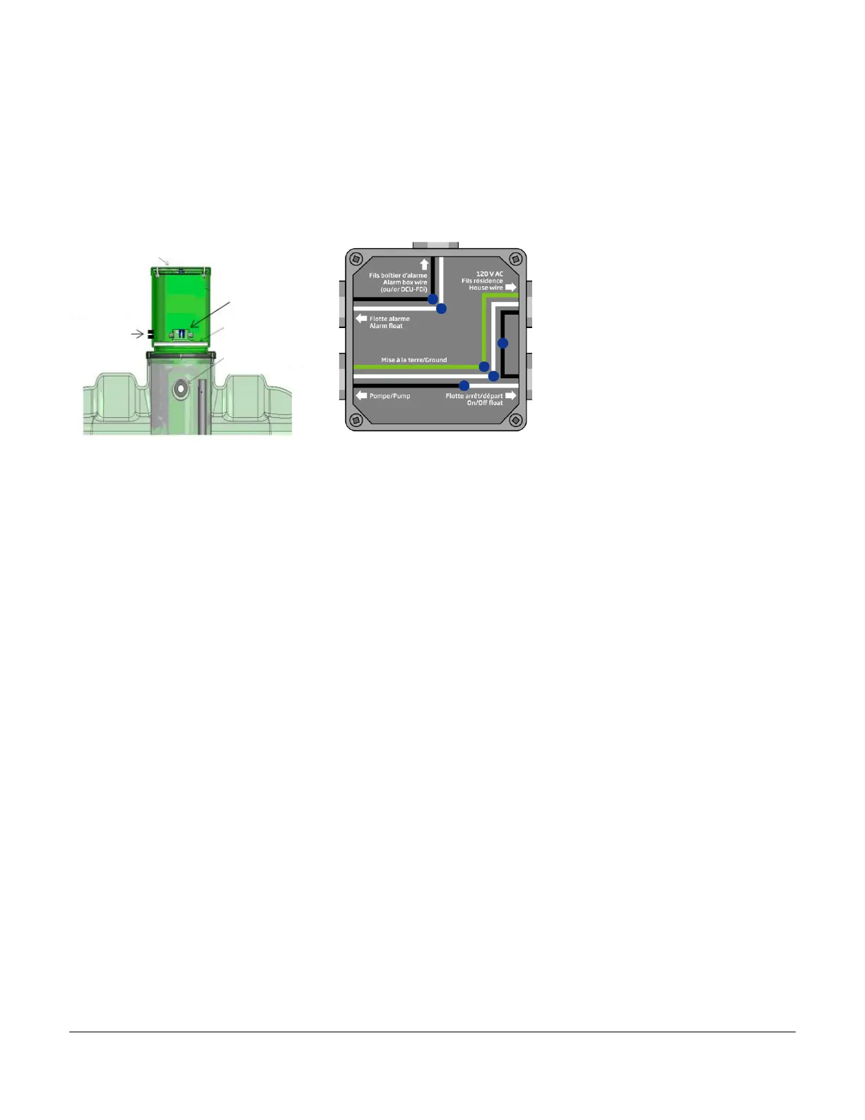
(13/16") in one of the sides of the access vault to later pass the two (2) connectors through that side. Regardless
of the model, pass the electrical wiring entering the system through these two (2) holes. Identify and insert the wires
in the junction box as per the electrical diagram on the following page. Make the electrical connections using the
watertight wire screw connectors provided to prevent water from affecting the electrical circuit. Follow the
diagram’s colour code. Also, the start-stop float’s white wire is connected to the pump’s black wire (“hot” wire). It
is strongly recommended to wrap the white wire with black electrical tape. Next, close the electrical junction box.
Pass the electrical wires arriving from the pumping unit through the groove of the insulating panel. Place the
insulating panel within the access with the electrical box on top of it and close the secondary access cover if
applicable.
Unless otherwise prescribed by State
regulation or local jurisdiction, use two
standalone breakers: one for the pump’s
power supply and the other for the alarm
box. Do not connect anything else to
these breakers (e.g., household
appliance). They are to serve exclusively
for the pump and alarm box.
 Loading...