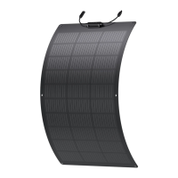
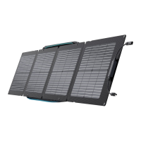
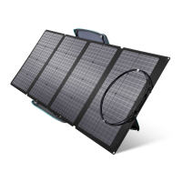
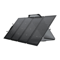
The EcoFlow 100 W Flexible Solar Panel is a component designed for solar energy systems, converting solar energy into DC electricity. It is intended for outdoor use and can be mounted on fixed outdoor objects, including vehicles and vessels, provided local and national regulations are observed.
Function Description:
The solar panel is a flexible module made of a special composite material, allowing it to bend to a certain degree for use on various roof surfaces. It utilizes monocrystalline silicon wafers to generate DC electricity. When exposed to direct sunlight, a single module can generate DC voltages greater than 24 V. Multiple modules can be connected in series to increase voltage or in parallel to increase current, depending on system requirements. The panel is equipped with a permanently connected junction box and 2.5 mm² (0.004 in²) wires, with bypass diodes integrated into the junction box for all modules.
Important Technical Specifications:
- Rated Power: 100 W (+/- 5 W)
- Open Circuit Voltage: 20.3 V
- Short Circuit Current: 6.3 A
- Maximum Operating Voltage: 17.1 V
- Maximum Operating Current: 5.9 A
- Temperature Coefficient of Rated Power: -(0.39+/-0.02)%/k
- Temperature Coefficient of Open Circuit Voltage: -(0.33+/-0.03)%/k
- Temperature Coefficient of Short Circuit Current: +(0.06+/-0.015)%/k
- Maximum System Voltage: 600 VDC (UL)
- Maximum Fuse Current: 15 A
- Solar Panel Weight: Approx. 2.3 kg (5.1 lbs)
- Dimensions: 1,055 x 612 x 25 mm (41.5 x 24.1 x 1.0 in)
- Operating Temperature Range: -20°C to 85°C (-4°F to 185°F)
- Certifications: FC, CE, RoHS, IP68
- Standard Test Conditions (STC): 1000 W/m² (92.9 W/ft²), AM1.5, 25°C (77°F)
Usage Features:
The EcoFlow 100 W Flexible Solar Panel is designed for ease of installation and integration into various solar photovoltaic systems.
- Flexibility: Its composite material allows for some bending, making it adaptable to different mounting surfaces, such as vehicle roofs. However, excessive bending should be avoided to prevent damage to the monocrystalline wafers.
- Mounting Options: The panel features six 8 mm (inside diameter) holes at its edges for fixing with optional adapter bolts. Alternatively, it can be secured using structural adhesive (e.g., Dow Corning) or double-sided adhesive foam tape (e.g., 3M) on the back. Regardless of the method, gaps between the panels and the mounting surface are crucial to maintain airflow and ensure proper heat dissipation, which contributes to prolonged service life and optimal power generation.
- Series and Parallel Connections: Modules can be connected in series to increase voltage or in parallel to increase current. For series connections, the positive terminal of one module connects to the negative terminal of the next. For parallel connections, positive terminals connect to positive, and negative terminals connect to negative. It is recommended to connect modules with the same electrical output in the same series to prevent efficiency loss.
- Optimal Performance:
- Sunlight Exposure: The panel should be positioned to receive direct sunlight without shading, as even small amounts of shade can significantly reduce power output. For maximum electricity generation, the module should face directly south in the Northern Hemisphere and directly north in the Southern Hemisphere.
- Temperature: Lower surface temperatures generally lead to higher power output.
- Safety: During installation and troubleshooting, it is crucial to cover the light-receiving surface with opaque material and disconnect terminals to prevent power generation. Only insulated tools approved for electrical installation should be used, and metal accessories should be removed to avoid electric shock. All local, regional, and national safety regulations must be followed.
- Labels: Each module includes a Nameplate Sticker providing product type, electrical parameters, weight, and dimensions, and an SN Code Sticker with a unique serial number. These labels should not be removed, as doing so voids the product warranty.
Maintenance Features:
Regular maintenance is recommended to ensure the optimal performance and longevity of the solar module.
- Cleaning: The flexible surface of the module should be cleaned with water and a soft sponge or cloth when necessary. Mild detergent can be used for stubborn dirt. Sharp or hard cleaning tools should be avoided to prevent scratching the surface. Cleaning is best performed in the morning or evening when sunlight is weak (irradiance ≤200 W/m²).
- Inspection: Electrical and mechanical connections should be inspected every six months to confirm they are clean, secure, and undamaged.
- Obstruction Prevention: Leaves and other objects should be prevented from covering the solar panel surface. Partial shading not only reduces power generation efficiency but can also cause excessive current in certain areas, potentially burning out components.
- Troubleshooting: In case of abnormal power generation, check for open circuits or poor connections, and measure the open circuit voltage of each module, both uncovered and completely covered with opaque material, to identify issues. If the voltage differs by more than 5% from the nominal value at an irradiance of ≥700 W/m², it indicates a poor electrical connection.
- Professional Assistance: All commissioning and maintenance of the solar module system should be carried out by qualified PV technicians. For any issues, a qualified expert should investigate and follow maintenance instructions for all system components, including brackets, charge regulators, inverters, and batteries.