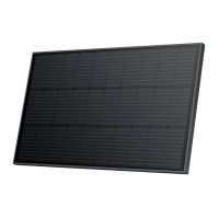
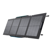
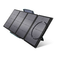
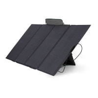
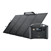
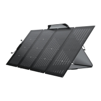
The EcoFlow 100 W Rigid Solar Panel is a photovoltaic module designed for outdoor use, converting solar energy into DC electricity. It is part of the EF-SG-M100 series and is intended to be mounted on fixed outdoor objects, including vehicles or vessels.
Function Description
The primary function of the EcoFlow 100 W Rigid Solar Panel is to generate DC electricity from sunlight. It can be connected in series to increase voltage or in parallel to increase current, allowing for flexible system configurations to meet various power demands. Bypass diodes are integrated into the junction box of all modules to prevent issues arising from power generation.
Important Technical Specifications
100W Rigid Solar Panel
- Rated Power: 100 W (+/-5 W)
- Open Circuit Voltage: 20.3 V
- Short Circuit Current: 6.3 A
- Maximum Operating Voltage: 17.1 V
- Maximum Operating Current: 5.9 A
- Temperature Coefficient of Rated Power: -0.39% / °C
- Temperature Coefficient of Open Circuit Voltage: -0.33% / °C
- Temperature Coefficient of Short Circuit Current: 0.06% / °C
- Maximum System Voltage: 600 VDC (UL)
- Maximum Fuse Current: 15 A
General
- Solar Panel Weight: Approx. 6.2 kg (13.7 lbs)
- Dimensions: 98 x 58.6 x 3 cm (38.6 x 23.1 x 1.2 in)
- Operating Temperature Range: -20°C to 85°C (-4°F to 185°F)
- Certifications: FC, CE, RoHS, IP68
The panels are made of monocrystalline silicon wafers. Each module has a unique serial number and a nameplate sticker providing product type, electrical parameters, weight, and dimensions measured under standard test conditions (STC: 1,000 W/m² (92.9 W/ft²), AM1.5, 25°C).
Usage Features
Installation:
- Mounting: The module must be mounted using the 12 reserved mounting holes in its frame (L*W: 11 × 7 mm / 0.4 × 0.3 in). The most common method involves using the four symmetrical holes near the center of the frame.
- Bolt Installation: Requires a special bolt kit (purchased separately) including z-shaped brackets, M6 hex bolts (with nuts), M6 large washers, M6 flat washers, M6 spring washers, and hex self-drilling screws (5.538 mm / 0.21.5 in).
- Grounding: The holes at the center of each long edge are used for grounding.
- Secure Mounting: Modules must be securely mounted at four or more points in opposite directions to withstand expected loads (wind, snow).
- Spacing: A gap of 12.7 mm (0.5 in) or larger should be maintained between modules.
- Airflow: When installing on a vehicle roof, a gap between the solar panel and the roof is crucial for airflow and heat dissipation.
- Orientation: For optimal electricity generation, the module should face directly south in the Northern Hemisphere and directly north in the Southern Hemisphere.
- Shade Avoidance: The module's surface should not be shaded, as even minimal shading can significantly reduce power output.
- Drain Hole: Do not block the drain hole at the bottom of the module.
- Electrical Connections: Modules can be connected in series (positive terminal of one to negative of the next) or parallel (positive to positive, negative to negative). It is recommended to connect modules with the same electrical output in the same series to prevent mismatching.
- Cable Sizing: The cross-sectional area of the cable and the connector capacity must match the maximum system short-circuit current to prevent overheating.
- DC Fuses: Must be appropriate for the module's overcurrent protection rating.
Safety Precautions:
- High Voltage: When exposed to direct sunlight, a single module can generate DC voltages greater than 24 V, which is potentially dangerous. Series connections increase total voltage, while parallel connections increase total current.
- Arcing Risk: Disconnecting wires connected to sun-exposed PV components can cause arcing, leading to burns or fire.
- Insulated Tools: Only use insulated tools approved for electrical installation when working with the system.
- Personal Protective Equipment: Avoid wearing metal rings, straps, earrings, nose rings, lip rings, or other metal devices during installation or troubleshooting.
- Module Covering: It is recommended to completely cover the light-receiving surface with opaque material during installation, and disconnect positive and negative terminals to prevent power generation.
- Flammable Materials: Ensure the installation site is free of flammable materials, especially when mounting on a vehicle roof.
- System Components: Comply with safety instructions for all other system components (cables, connectors, controllers, charge regulators, inverters, batteries).
- Module Integrity: Do not step, walk, stand, or jump on the module to avoid micro-cracks. Do not use sharp tools to score, cut, slice, or slash the module, especially the back plate.
- Electrical Contacts: Keep all electrical contacts and connectors clean and dry.
- Modifications: Do not attempt to disassemble the module, remove nameplates, or modify the module's frame, as this will void the warranty.
- Surface Treatment: Do not apply paint, adhesives, or substances that block the battery cell from light. Do not expose the module surface to artificially centralized amplified sunlight.
- Legal Compliance: Observe all local, regional, and national laws and statutory regulations during installation, especially when installing on a vehicle or vessel.
Performance Considerations:
- Power Output Fluctuations: Actual power output may vary from the nominal 100 W due to factors like light intensity (time of day, weather), surface temperature (lower temperatures yield more power), sunlight angle, and panel shading.
- Optimal Conditions: Nominal power ratings are based on 1,000 W/m² (92.9 W/ft²) in AM1.5 conditions with a panel temperature of 25°C. Real-world conditions typically yield 70-80 W in a 100 W panel on a clear day with 800-900 W/m² irradiance and 50°C panel temperature.
- Series/Parallel Connections: While series connections are possible, they are not recommended without careful consideration of energy storage controller requirements to avoid power loss. Parallel connections are recommended to increase current, provided the energy storage system supports higher input current and appropriate wiring is used.
Maintenance Features
- Cleaning: Clean the glass surface of the module with water and a soft sponge or cloth when necessary. Mild detergent can be used for stubborn dirt. Avoid sharp or hard cleaning tools. It is recommended to clean in the morning or evening when sunlight is weak (irradiance ≤200 W/m² / 18.6 W/ft²). Regular cleaning helps maintain optimal power output by removing dust and foreign objects.
- Inspections: Inspect electrical and mechanical connections every six months to ensure they are clean, secure, and undamaged.
- Obstruction Prevention: Prevent leaves and other objects from covering the solar panel surface, as partial shading reduces power generation efficiency and can cause excessive current, potentially burning out components.
- Troubleshooting: In case of abnormal power generation, check wiring for open circuits or poor connections, and measure the open circuit voltage of each module (both covered and uncovered) to identify issues. A voltage difference greater than 5% from the nominal value at ≥700 W/m² irradiance indicates a poor electrical connection.
- Professional Assistance: EcoFlow recommends that all commissioning and maintenance be carried out by qualified PV technicians. For any issues, a qualified expert should investigate and follow maintenance instructions for all system components (brackets, charge regulators, inverters, batteries).