Installer manual ecoGEO
53
5.5. Outside temperature probe
The outside temperature probe, supplied with the heat pump, has to be installed for the heat pump to work properly. Follow the
instructions below to install it.
Install the outside probe in a well ventilated area, but protected from wind and rain.
Do not install the outside probe at a distance of less than 1 m from windows or doors to avoid the effect of possible currents
of warm air.
Use a shielded 2-pole cable to prevent interferences.
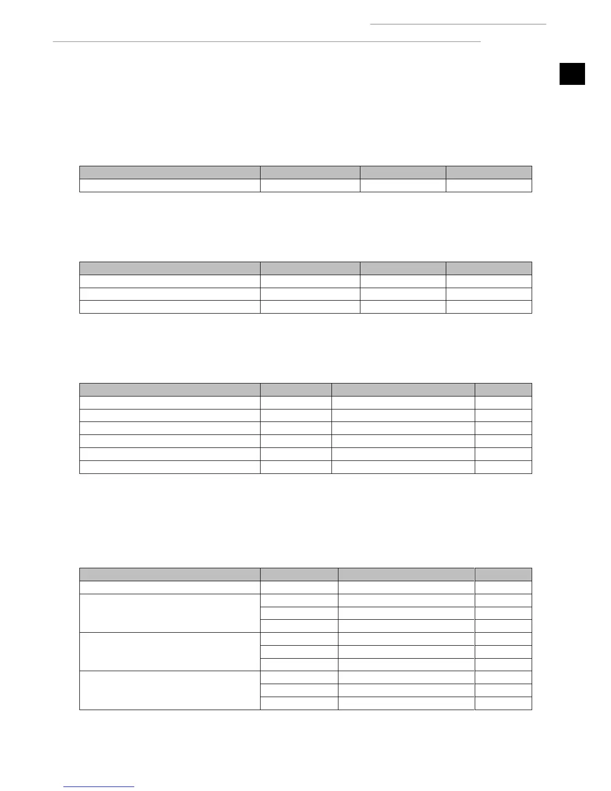
Outside temperature probe
Table 1.1. Outside temperature probe connection terminals.
5.6. External storage systems
These can be used to control DHW storage, heating and cooling temperatures using temperature probes.
Heating buffer storage tank
Cooling buffer storage tank
Table 1.2. Connection terminals for outlet units.
5.7. External production equipment
These are used to control production equipment handling of the various services, such as bypass valves or circulatory pumps.
Heating / cooling consumption
Activation 230Vac / 2A maximum
Active cooling production
Activation 230Vac / 2A maximum
Passive cooling production
Activation 230Vac / 1A maximum
Activation 230Vac / 2A maximum
Activation 230Vac / 2A maximum
Activation 230Vac / 2A maximum
Table 1.3. Auxiliary equipment connection terminals.
5.8. DG1 – SG4 Outlet Units
The heat pump can control a direct outlet unit (DG1) and three outlet units with mixture (SG2, SG3 and SG4). Unit activation can be
controlled according to heating or cooling demand. In addition, the units with mixture can measure the unit's outlet temperature
and generate a regulation signal for the 3-way modulating valve.
Activation 230Vac / 2A maximum
Valve regulation 0 – 10Vdc
Activation 230Vac / 2A maximum
Valve regulation 0 – 10Vdc
Activation 230Vac / 2A maximum
Valve regulation 0 – 10Vdc
Activation 230Vac / 2A maximum
Table 1.4. Connection terminals for outlet units.