Installer manual ecoGEO
35
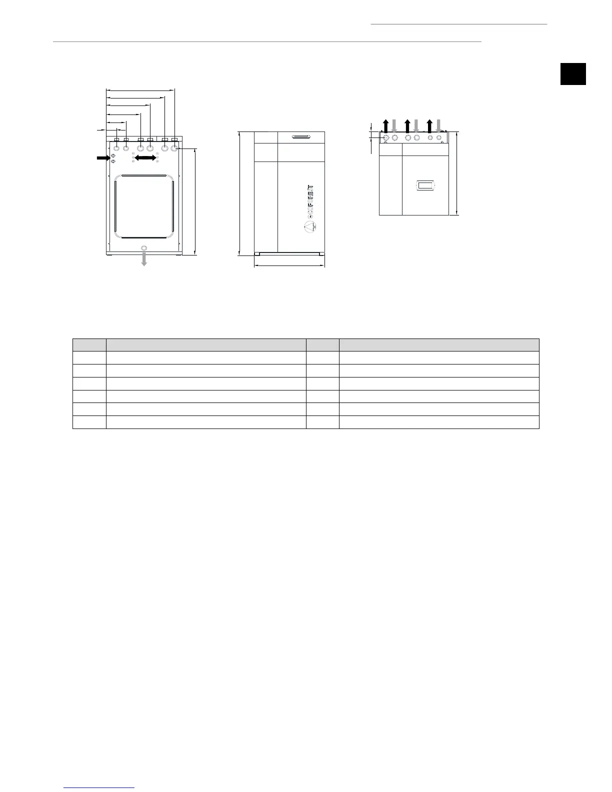
Figure 1.2. Overall dimensions and hydraulic connections of the ecoGEO Basic model (Amounts in mm).
Heating / cooling supply; G1-1/4” Male
Tap water inlet; G1" Female
Heating / cooling return; G1-1/4” Male
Brine supply; G1-1/4” Male
DHW recirculation return; G3/4” Female
Brine return, G1-1/4 Male
DHW exchanger intake; G1” Male
DHW exchanger return; G1” Male
Table 1.1. Hydraulic connections key.
All the models are prepared for pipe connection both at the top and at the rear.
The factory installation is prepared for connection at the top. To connect at the rear, the connection fittings installed at the top must
be exchanged with the blind cable glands installed at the rear.
2.3. Unpacking
To unpack the heat pump, remove the wooden box carefully, remove the pallet anchoring screws and perform a check to make sure
the heat pump has not been damaged during transportation.