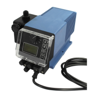
4.2.2.5 EMP III Connector assignments of slot IV (4-terminal)
Input for diaphragm breakage monitoring (only EMP III)
Pin Assignment
1 Output 5 V, DC (loadable with max. 50 mA)
2 not assigned
3 Input diaphragm breakage monitoring
4 GND (┴)
4.2.3 Control inputs and outputs EMP IV
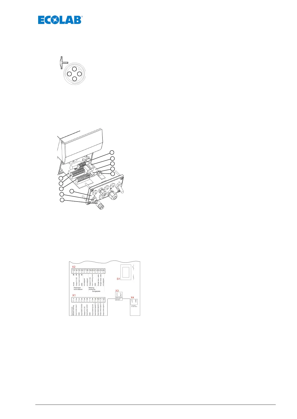
Übersicht Steuerplatine
1 Switch (without function!)
2 Connection terminals (X2)
3 Connection terminals (X1)
4 Suction pipe connection
5 Cover cap
6 Front panel
7 Connection for "On/Off" switch
8 Connection terminals (X3)
9 PCB
10
Selector switch for empty signal contact (normaly open/normaly
closed) of empty or fault report relay
11 Installed Dongle-Plate E60
After the lower part of the front has been removed (pos. 6), the terminal
box becomes accessible for drive and output signals. The PCB (pos. 9)
may be slightly pulled out from the pump housing together with the
connection terminals (pos. 2, 3, 7 & 8). The terminals can be detached.
For the connection of a suction lance, the plug (pos. 4) is provided at the front. If no suction lance is used, the
supplied cover cap (pos. 5) with the integrated bridges must be attached. With the selector switch (pos. 10)
the contact of the fault or empty signal relay can be switched from normally open function to normally closed
function.
4.2.3.1 EMP IV Terminal board diagram
Pin See
X1
Ä
Chapter 4.2.3.2 ‘EMP IV Connector Assignments
Terminal X1’ on page 16
X2
Ä
Chapter 4.2.3.3 ‘ EMP IV Connector
Assignments Terminal X2’ on page 16
X3
Ä
Chapter 4.2.3.4 ‘EMP IV Connector Assignments
Terminal X3’ on page 16
X4
Operating instructions Art. No. 417101799 EMP IV.
S
Device installation
15 MAN033535 Rev. 06-04.2020
 Loading...