46
39-04/- 0/33)",%#!53% 2%-%$9
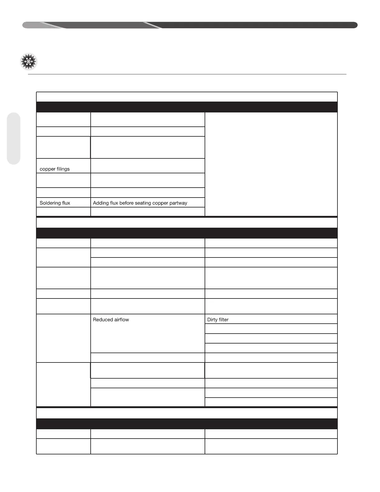
Moisture Poor evacuation on installation or during service
In each case, the cure is the same. Recover refrigerant,
flush system. Add filter driver, evacuate, and recharge.
High head pressure Noncondensibles air
Unusual head and
suction pressure
readings
Wrong refrigerant or mixed refrigerants
Foreign matter –
Copper tubing cuttings
Copper oxide Dirty copper piping or nitrogen not used when
brazing
Welding scale Nitrogen not used during brazing
Excess soft solder Wrong solder material
,/33/&,5"2)#!4)/.
39-04/- 0/33)",%#!53% 2%-%$9
Compressor failures Vapor line tubing too large Reduce tubing size to improve oil return.
Low suction pressure Low charge Check system charge.
Refrigerant leaks Repair and recharge.
Cold, noisy
compressor –
Slugging
Dilution of oil with refrigerant Observe piping guidelines.
Noisy compressor Migration Check stater heat and compressor thermistor.
Cold, sweating
compressor
Flooding Check system charge.
Low load
Dirty coil
Wrong duct size
Restricted duct
Thermostat setting Advise customer.
Short cycling of
compressor
Cycling or faulty high or low pressure control Check pressure and address cause of any abnormal
pressure. Replace control if faulty.
Loose wiring Check all control wires.
Thermostat In supply air stream, out of calibration
Customer misuse
,)15)$2%&2)'%2!.43,5'').'
39-04/- 0/33)",%#!53% 2%-%$9
On start-up Incorrect piping Review pipe size guidelines.
EXV hunting when
running
Faulty EXV components Check EXV, suction pressure transducer, and suction
thermistor for operation.
#/.4!-).!4)/.
9.3 Service Analyzer Charts (cont.)
9.0 DIAGNOSTICS & TROUBLESHOOTING
Diagnostics


 To Next Page