4 of 10
4. WIRING
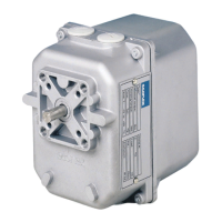
4.1 After having installed AB1 gear motor and before fastening it mechanically to
the device it has to operate, proceed with wiring and earthing.
4.2 Wiring diagrams are reported in the attached technical bulletin and on the
plate inside the cover.
4.3 WARNING!
Before servicing make sure, that power supply is disconnected by means of
the two-pole-switch [phase and neutral]; in case of non-observance,
damages to people and equipments may occur.
4.4 In order to accede to the internal wiring terminal board, remove the cover
by loosening the 4 fastening screws.
4.5 Two threaded holes for the fitting of the conduit plugs PG 13.5 are present
on the frame of the AB1 gear motor.
4.6 All wires must comply with local prescriptions and, in any case, their section
must be ranging between 1 and 1.5 mm
2
. Connection piping recommended
H07V-U…G1.5 mm
2
.
4.7 Connection wiring diagrams show AB1 gear motor at end position closed
[0°].
4.8 Auxiliary microswitches are single-pole double through and voltage-free.
4.9 The rating of auxiliary microswitches is 5[1]A/250V a.c.
4.10 If a potentiometer is installed, its resistance value is indicated on the
nameplate.
4.11 Make sure that power supply and system frequency correspond to the values
indicated on the gear motor plate.
4.12 Low-tension signalling cable [tension lower than 48V] must be laid
separately from the higher-tension conduits [tension higher than 48V]. In
case they are laid in a single channel, screened cables must be used.