9 of 10
9.1.9 Once all adjustments have been carried out return the key inside the AB1
gear motor and reinstall the cover by fastening the 4 screws.
9.1.10 Reinstall the control lever system of the AB1 gear motor and test
functioning of the whole system.
9.2 Potentiometer/s
9.2.1 The potentiometer shaft is frictioned and is accessible from the upper side
inside the gear motor.
9.2.2 Disconnect the cables connected with the regulation system from the
respective terminals n. 30, 31 and 32 [Pot. A] and, if necessary, n. 33, 34
and 35 [Pot. B].
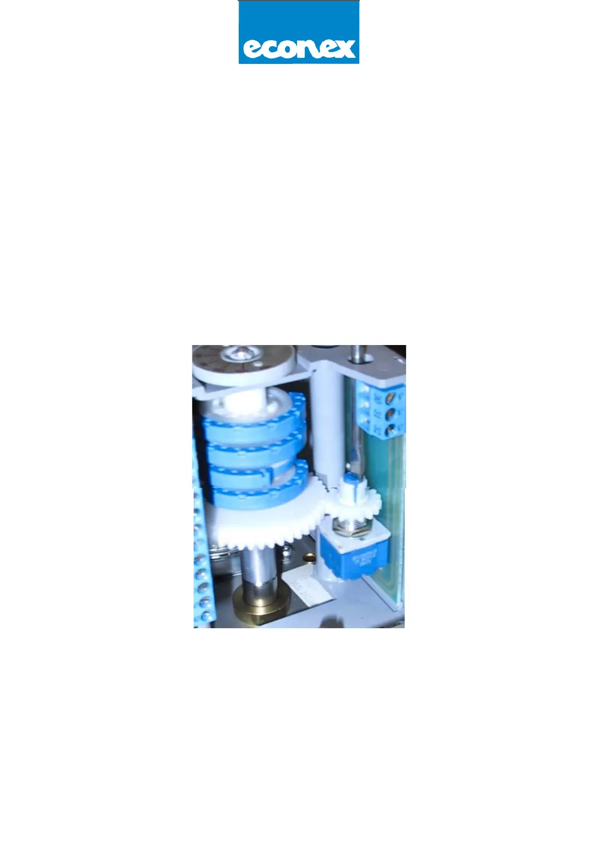
9.2.3 By means of a suitable screwdriver with 5 mm cut rotate the potentiometer
shaft and measure the resistance value of 0 Ohm between terminals n. 31
and 32 and, if necessary, also between terminals n. 34 and 35 when the
gear motor is closed [picture 2].
Picture 2
By rotating the potentiometer:
● clockwise 3 the resistance value increases
● counter dock wise 4 the resistance value decreases
9.2.5 The gearbox between the gear motor shaft and the potentiometer shaft is
foreseen for a 90° rotation angle. Hence should the gear motor opening be
reduced with a rotation angle lower than 90°, the variation of the
potentiometer resistance value will be proportionally reduced.
If, on the contrary, the rotation angle has been wrongly adjusted over 90°
there will be no increase in the resistance value beyond the plate maximum
value.