EasyManua.ls Logo

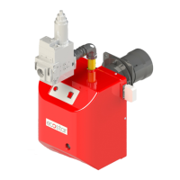
ECOSTAR ECO 250 User Manual

Default Icon
78 pages
To Next Page IconTo Next Page
Page #1 background imageLoading...
Page #1 background image
08.03.2024 Rev. 00
www.ecostar.com.tr
DUOBLOCK HEAVY OIL BURNERS INSTALLATION,
OPERATING AND MAINTENANCE MANUAL
MODULATING OPERATION (ELECTRONIC)
ECO 250
ECO 300
ECO 350
ECO 400
ECO 450
ECO 500
ECO 600
ECO 700
ECO 800
ECO 900

Other manuals for ECOSTAR ECO 250

Questions and Answers:

ECOSTAR ECO 250 Specifications

General IconGeneral
BrandECOSTAR
ModelECO 250
CategoryBurner
LanguageEnglish

Summary

1. WARNINGS

1.1. Warning Symbols and Descriptions

Explains the meaning of various warning symbols used in the manual.

1.2. General Safety Rules

Outlines essential safety precautions for installation, operation, and maintenance.

2. TERMS OF WARRANTY

2.1. Out of Warranty Conditions

Lists conditions under which the product warranty is invalidated.

3. BURNER'S GENERAL FEATURES

3.1. Purpose of Use and Work Limits of Burners

Specifies the intended applications and operational boundaries of the burners.

3.2. Code Key

Provides a breakdown of the model code to understand burner specifications.

4. TECHNICAL DATA

4.1. Capacity Table

Details the capacity (MW, kcal/h, kg/h) for different burner models.

4.2. Burner Dimensions

Provides physical dimensions and mounting information for various burner models.

5. INSTALLATION

5.1. Burner Installation Picture

Illustrates the correct method for installing the burner onto a boiler or application.

6. COMMISSIONING

6.1. General Controls

Lists necessary checks and procedures before initiating burner operation.

6.2. Combustion Adjustment

Details the process for adjusting combustion settings for optimal performance.

6.3. Photocell

Information on the photocell, its function, and maintenance.

6.4. Nozzle

Describes the fuel nozzle, its types, and installation.

6.5. Curves According To Fuel Consumption (Fuel Nozzles)

Graphical representation of fuel consumption based on nozzle type and output.

6.6. Oil Adjustment Regulator

Explains the function and adjustment procedure for the oil regulator.

6.7. Oil Burner Ring Line

Presents the P&ID diagram for the heavy oil burner ring line.

6.8. Servomotor Adjustment

Details the adjustment and types of servomotors used for burner control.

6.9. Emission Measurement

Outlines procedures and reference values for measuring emissions.

6.10. Program Relay

Describes the program relay and its role in the control system.

Operating Control and Displays

Display Overview

Explains the display interface elements and information shown.

Control Key Functions

Details the operation of navigation keys for menus and settings.

Menu Functions

INFO Path

Accesses information about the burner, errors, software version, and device status.

MANUAL Path

Allows manual control of the burner's start/stop and firing rate.

SETTINGS Path

Enables configuration of parameters like password, burner settings, and air/fuel control.

BT300 Connecting Diagram

Terminal Designation and Function

Explains the purpose and electrical ratings of BT300 connection terminals.

Leakage Test for Main Gas Valves

Gas Valve Leakage Test Procedure

Illustrates the step-by-step process for performing a leakage test on main gas valves.

ETAMATIC OEM System

Etamatic OEM Digital Inputs

Lists and explains the meaning of the digital inputs for the ETAMATIC OEM system.

ETAMATIC Connection Diagram

Shows the wiring diagram for the ETAMATIC system, including power and signal connections.

Fault Codes

Fault Codes and Descriptions

Comprehensive list of fault codes, restart methods, and descriptions for burner operation issues.

7. MAINTENANCE

7.1. Weekly Maintenance

Outlines the routine cleaning and adjustment procedures performed weekly.

7.2. Monthly Maintenance

Describes comprehensive monthly checks for burner and peripheral components.

7.3. Seasonal Maintenance

Details maintenance tasks performed when restarting after long periods of shutdown.

8. TROUBLESHOOTING

Troubleshooting Guide

Provides a table of common problems, their causes, and suggested solutions for troubleshooting.

9. PERIODICAL FLUE GAS MEASUREMENT REPORT

Flue Gas Measurement Log

A log sheet template for recording fuel consumption, CO, O2, CO2, NOx, Yield, and Flue Temp.

10. AFTER SALES SERVICES

Customer Support and Recommendations

Provides contact information for service requests and recommendations for product use.

11. NOTES

User Observations Log

A space for users to record measurements and observations.

Related product manuals