EasyManua.ls Logo

Ecotechnics XK360 User Manual

Default Icon
48 pages
To Next Page IconTo Next Page
Page #1 background imageLoading...
Page #1 background image
The data, information and descriptions, and the technology described herein are the exclusive intellectual property of Ecotechnics S.p.A. and constitute industrial
secrets. Said information is communicated in strict confidentiality; said information may be used only for the purpose for which it is communicated; said information
may not be divulged, communicated, or revealed to third parties and/or reproduced by any means for any reason whatsoever; said information is protected under
applicable Italian competition and industrial property law.
Service manual VA500-VA750 ed.1 ver.5.05 [MANU360.SA0].doc pag.1 - 18/10/2005

Table of Contents

Question and Answer IconNeed help?

Do you have a question about the Ecotechnics XK360 and is the answer not in the manual?

Ecotechnics XK360 Specifications

General IconGeneral
BrandEcotechnics
ModelXK360
CategoryService Equipment
LanguageEnglish

Summary

INTRODUCTION

PREPARATION FOR REMOVAL AND DISASSEMBLY

Steps for preparing the machine before removal and disassembly.

REPLACEMENT PARTS

Guidance on using genuine manufacturer parts for replacements.

CHECKING THE CONNECTIONS

OPERATING CYCLE

RECOVERY-RECYCLING PHASE

Detailed description of the refrigerant recovery and recycling process.

VACUUM PHASE

Procedure for evacuating air and non-condensable gases from the system.

FILLING PHASE

Process for recharging new oil and refrigerant into the A/C system.

THE MACHINE

BASIC COMPONENTS

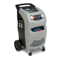
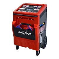
Identification and description of the main components of the machine.

CONTROLS AND CONTROL SYSTEM

FUNCTION SELECTOR KEYBOARD

STATUS AND ALARM PANEL

ROUTINE MAINTENANCE

FILLING THE MACHINE BOTTLE

Procedure for refilling the machine's internal refrigerant bottle.

VACUUM PUMP

Routine maintenance for the vacuum pump, including oil checks and changes.

REPLACING THE DRYER FILTERS

FILLING THE NEW OIL TANK

EMPTYING THE USED OIL TANK

SPECIAL MAINTENANCE

BOTTLE SCALE CALIBRATION

Procedure for calibrating the refrigerant bottle scale.

ELECTRONIC VALVE CLEANING OR SUBSTITUTION

Steps for cleaning or replacing electronic solenoid valves.

CHANGING THE UNITS OF MEASURE (KG→LBS OR LBS→KG)

How to switch between metric and imperial units.

TEST OF THE MACHINE

Procedures for testing the machine's functionality.

TROUBLESHOOTING

FULL BOTTLE ALARM

Actions to take when the full bottle alarm is triggered.

EMPTY BOTTLE ALARM

Actions to take when the empty bottle alarm is triggered.

SERVICE ALARM

Troubleshooting steps for the service alarm.

HIGH PRESSURE ALARM

Resolving issues related to high pressure in the system.

NO DISPLAY WHEN MAIN POWER SWITCH IS ON

Diagnosing and fixing issues with the display when power is on.

FLUCTUATION OF THE READING OF THE REFRIGERANT

Addressing unstable refrigerant readings.

VACUUM PUMP DOESN'T START

Troubleshooting when the vacuum pump fails to start.

VACUUM PUMP RUNS, BUT LOW SIDE GAUGE DOES NOT REGISTER AN APPROPRIATE VACUUM

Diagnosing low vacuum readings despite pump operation.

THE MACHINE DOESN'T FINISH THE REFILLING

Resolving issues where the refilling process is incomplete.

THE MACHINE DOESN'T REFILL THE OIL

Troubleshooting the oil refilling function.

THE MANOMETERS DON'T READ THE PRESSURE OF THE A/C SYSTEM

Fixing problems with pressure gauge readings.

PROBLEMS DURING THE DOWNLOAD OF THE SOFTWARE

Resolving issues with software download and communication.

SCALE DOESN'T READ THE WEIGHT

Troubleshooting errors with the weight scale function.

GAIN-OF-WEIGHT IMPLIES READING DECREASE OF THE SCALE

Diagnosing scale reading decreases during weight gain.

THE MACHINE DOESN'T FINISH THE RECOVERY

ALARM MESSAGES

ER02

Explanation of the ER02 alarm code and its causes.

ER01

Explanation of the ER01 alarm code and its causes.

HIGH PRESSURE LED

Indication and meaning of the high pressure LED.

BOTTLE EMPTY LED

Indication and meaning of the bottle empty LED.

FULL BOTTLE LED

Indication and meaning of the full bottle LED.

SERV

Indication and meaning of the SERV indicator.

HEATER (ONLY MODEL XK360)

Function of the heater indicator for specific models.

SUGGESTED SPARE PARTS

TECHNICAL DETAILED LISTS

WIRING

30 kg load cell wiring

Wiring diagram for the 30 kg load cell.

Power supply wiring

Diagram for the power supply connections.

Main ground wiring

Wiring diagram for the main ground connection.

Main switch wiring + choke

Wiring details for the main switch and choke assembly.

2 electronic valve wiring (mate_n_lock)

Wiring diagram for two electronic valves using Mate-N-Lock.

3 electronic valve wiring (mate_n_lock)

Wiring diagram for three electronic valves using Mate-N-Lock.

Heater pressure switch wiring (prs4075) (ONLY MODEL XK360)

Wiring for the heater pressure switch on specific models.

Low pressure switch wiring (prs4175)

Wiring diagram for the low pressure switch.

Safety pressure switch wiring (prs4305)

Wiring diagram for the safety pressure switch.

Compressor wiring

Wiring connections for the compressor.

Condenser fan wiring

Wiring diagram for the condenser fan.

Vacuum pump wiring

Wiring connections for the vacuum pump.

Bottle heater wiring (ONLY MODEL XK360)

Wiring for the bottle heater on specific models.

Bottle temperature probe wiring (ONLY MODEL XK360)

Wiring for the bottle temperature probe on specific models.

HYDRAULICAL DIAGRAM

WIRING DIAGRAM

ELECTRONIC BOARD

SCH4000/SCH4001 VALUE_7/9 MOTHERBOARD

Details of the SCH4000/SCH4001 VALUE_7/9 motherboard.

EXPLODED VIEW KEY

MODEL XK360

Exploded view and parts list for Model XK360.

MODEL XK385

Exploded view and parts list for Model XK385.

MANIFOLD

PIPING

CHECK VALVE [GRVLV05]

SOLENOID VALVE [VLV1550]

NOTE

Related product manuals