13
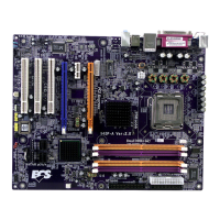
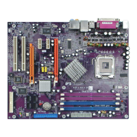
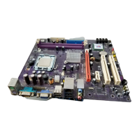
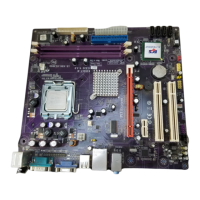
Installing the Motherboard
Installing Hardware
Installing the Processor
Caution: When installing a CPU heatsink and cooling fan make sure that
you DO NOT scratch the motherboard or any of the surface-mount resistors
with the clip of the cooling fan. If the clip of the cooling fan scrapes across
the motherboard, you may cause serious damage to the motherboard or its
components.
On most motherboards, there are small surface-mount resistors near the
processor socket, which may be damaged if the cooling fan is carelessly
installed.
Avoid using cooling fans with sharp edges on the fan casing and the clips.
Also, install the cooling fan in a well-lit work area so that you can clearly see
the motherboard and processor socket.
Before installing the Processor
This motherboard automatically determines the CPU clock frequency and system bus
frequency for the processor. You may be able to change these settings by making changes to
jumpers on the motherboard, or changing the settings in the system Setup Utility. We
strongly recommend that you do not over-clock processors or other components to run
faster than their rated speed.
This motherboard has an LGA775 socket. When choosing a processor, consider the perfor-
mance requirements of the system. Performance is based on the processor design, the clock
speed and system bus frequency of the processor, and the quantity of internal cache memory
and external cache memory.
Warning: Over-clocking components can adversely affect the reliability of
the system and introduce errors into your system. Over-clocking can per-
manently damage the motherboard by generating excess heat in compo-
nents that are run beyond the rated limits.
Power Switch
Supporting the power on/off function requires connecting pins 6 and 8 to a momentary-
contact switch that is normally open. The switch should maintain contact for at least 50 ms
to signal the power supply to switch on or off. The time requirement is due to internal de-
bounce circuitry. After receiving a power on/off signal, at least two seconds elapses before
the power supply recognizes another on/off signal.