30
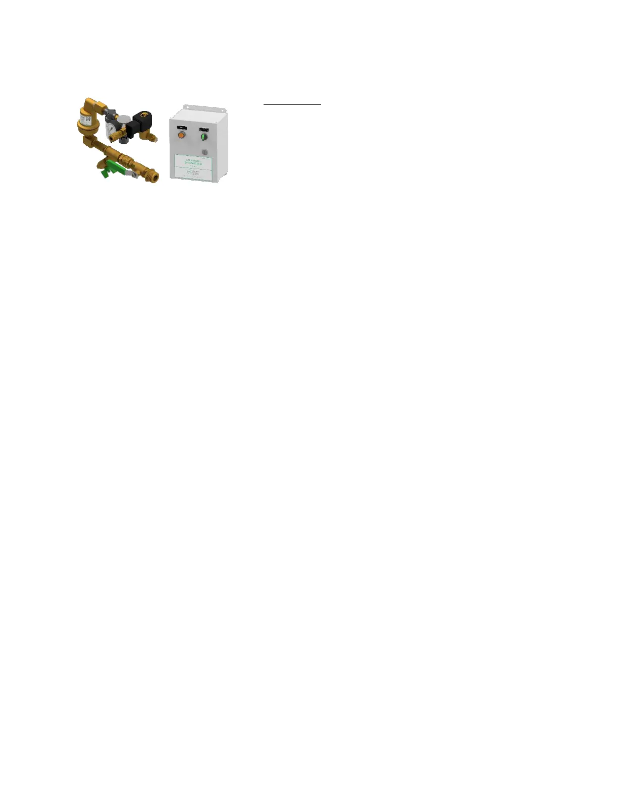
ECS SMART Vent - PSV-D/DE
Specifications
Stock Number: PSV-D/DE
Service Pressure: Up to 175 PSIG (12 Bar)
System Connection: 1” NPT Male
Temperature Range: 40°F to 120°F (4.5°C to 49°C)
Dimensions:
Vent Assembly: 13.5” (W) X 7.5” (H) X 4.25” (D)
(343mm (W) X 191mm (H) X 108mm (D))
Control Box: 8” (W) X 10” (H) X 6” (D)
(203mm (W) X 254mm (H) X 152mm (D))
Support Hanger Not Required
General Description
The ECS SMART Vent provides oxygen venting in dry pipe and preaction fire sprinkler systems. As a fire
sprinkler system is filled with a continuous supply of nitrogen gas from the Nitrogen Generator System,
the PSV-D/DE allows oxygen rich gas to be vented from the fire sprinkler system. Over a short period of
time the Vent will almost completely remove oxygen from the fire sprinkler system (less than 2% oxygen).
The Vent is equipped with a levered float valve that prevents water from passing through the restricted
venting orifice when water enters the fire sprinkler system. The in-line filter protects the restricted venting
orifice from contaminants from the sprinkler system. A backpressure regulator is included to prevent total
system depressurization from the vent assembly during the venting process. The restricted venting orifice
allows oxygen to be vented from the fire sprinkler system at a controlled rate to achieve a minimum of
98% nitrogen concentration. A special push fitting is provided to receive 5/32” tubing when the vent is
used in conjunction with the SMART Gas Analyzer.
The SMART Vent is equipped with an electronic solenoid valve that must be wired to the electric control
box (conductors not included). The control box will automatically close the vent once the desired nitrogen
concentration has been reached. The control box is equipped with an on/off switch and a vent button to
provide a means to restart of the venting process should oxygen be reintroduced into the fire sprinkler
system.
Installation Instructions
1. The SMART Vent includes two (2) separate components. The first component is the vent assembly
equipped with a ball valve to be connected to the fire sprinkler riser. The contractor must install a
1” outlet (welded or mechanical) to connect the vent assembly to the sprinkler system on the system
side of the main control valve. The isolation ball valve must remain in the closed position until the
nitrogen generator system has been commissioned.
NOTE: The vent assembly does not require a support hanger.
2. Install the vent assembly in a level position. Recommended mounting height is 5’-10’ (2-3m) above the
finished floor, but a minimum of 2’ (.6m) above the dry pipe or preaction control valve.
NOTE: Piping to the vent assembly cannot be installed in a configuration that would trap water and
prevent drainage to the sprinkler system; a water trap impedes the ability of the vent assembly
to vent oxygen from the fire sprinkler system.
 Loading...