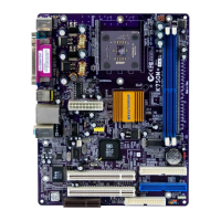
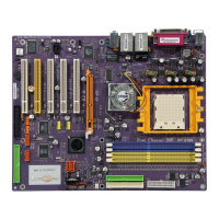
Table of Mainboard Components
Label Component
ATX1 Standard 20-pin ATX power connector
AUDIO1 Front panel MIC/Speaker Out header
BAT1 Three volt realtime clock battery
CD1 CD-in connector
CNR1 Communications Networking Riser slot
CPUFAN1 CPU cooling fan
CPU Socket Socket A for AMD Athlon/Duron CPUs
DDR1 ~ DDR2 Two 184-pin DDR DIMM sockets
FDC1 Floppy disk drive connector
IDE1 Primary IDE channel
IDE2 Secondary IDE channel
IR1 Infrared cable header
JP1 Clear CMOS jumper
JP2 USB card reader connector
PCI1 ~ PCI2 Two 32-bit add-on card slots
PWRFAN1 Power fan connector
SPK1 Speaker connector
SW1 Panel connector for case switches and LEDs
SYSFAN1 System cooling fan
USB2 Connector for front panel USB ports
This concludes Chapter 1. The next chapter explains how to install the main-
board.
6