USB2: Extended USB header
The mainboard has USB ports installed on the rear edge I/O port array. Some
computer cases have a special module that mounts USB ports at the front of
the case. If you have this kind of case, use auxiliary USB connectors USB2 to
connect the front-mounted ports to the mainboard.
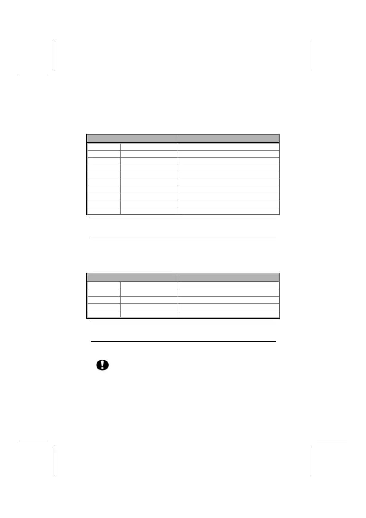
Pin Signal Name Function
1 VREG_FP_USBPWR0 Front Panel USB Power
2 VREG_FP_USBPWR0 Front Panel USB Power
3 USB_FP_P0- USB Port 0 Negative Signal
4 USB_FP_P1- USB Port 1 Negative Signal
5 USB_FP_P0+ USB Port 0 Positive Signal
6 USB_FP_P1+ USB Port 1 Positive Signal
7 GND Ground
8 GND Ground
9 KEY No pin
10 USB_FP_OC0 Overcurrent signal
Note: Please make sure that the USB cable has the same pin assignment as indi-
cated above. A different pin assignment may cause damage or system
hang-up.
JP2: USB Card Reader connector
This connector is for connecting internal USB card reader. You can use a card
reader to read or transfer files and digital images to your computer.
Pin Signal Name Function
1 USBVCC +5V
2 USB1- Data signal port 1-
3 USB1+ Data signal port 1+
4 GND Ground
5 Key No pin
Note: The JP2 is shared with one of the USB ports of the I/O back panel. The
USB port is located beside the serial port connectors. See “Connecting I/O
Devices” for more information.
Please check the pin assignment of the cable and the USB header on
the mainboard. Make sure the pin assignment will match before plug-
ging in. Any incorrect usage may cause unexpected damage to the
system.
20